A few days ago I was curious to know how my Hart 20V battery was wired. I use my Hart battery for almost all of my power tools while working.
It is one of the most reliable batteries in the market and I wanted to know what makes it that level of reliability by checking its wiring so that it would help me fix it in future or modify it to meet my specific requirements.
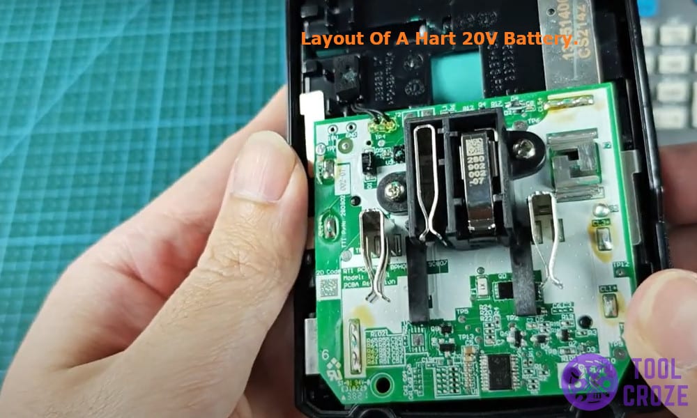
I have already tested Makita, Kobalt and other batteries but Hart had a very different layout than the other batteries I have tested.
But first, I also have a short video about this topic which you can watch below. I’m sure it will help you a lot to better understand the things discussed in this article.
Pinout Wiring Diagram of a Hart 20v Battery
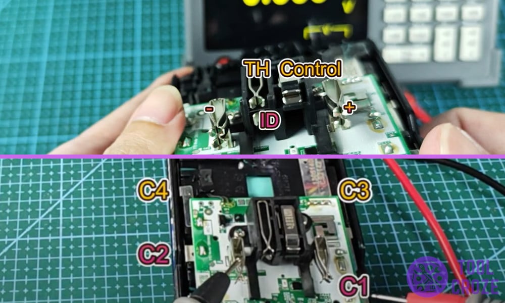
Five pints are used instead of the usual three and I had to dig in and find out what each one of them does. Here is a simple pinout diagram of Hart 20V battery based on what I found.

I grabbed my multimeter and set it up to find what was going on. I started by opening the top cover of the battery and found out that there were a total of 5 pins, this was unusual as most of the batteries only had 3 pins but Hart was different.
These 5 pins were, Positive pin and a Negative Pin, a pin for Thermistor (TH) that reads and sends the temperature of the battery to the charger to trigger the safety hot and cold delay in case of emergencies.
Related: 3 Ways to Reset HART 20V Battery
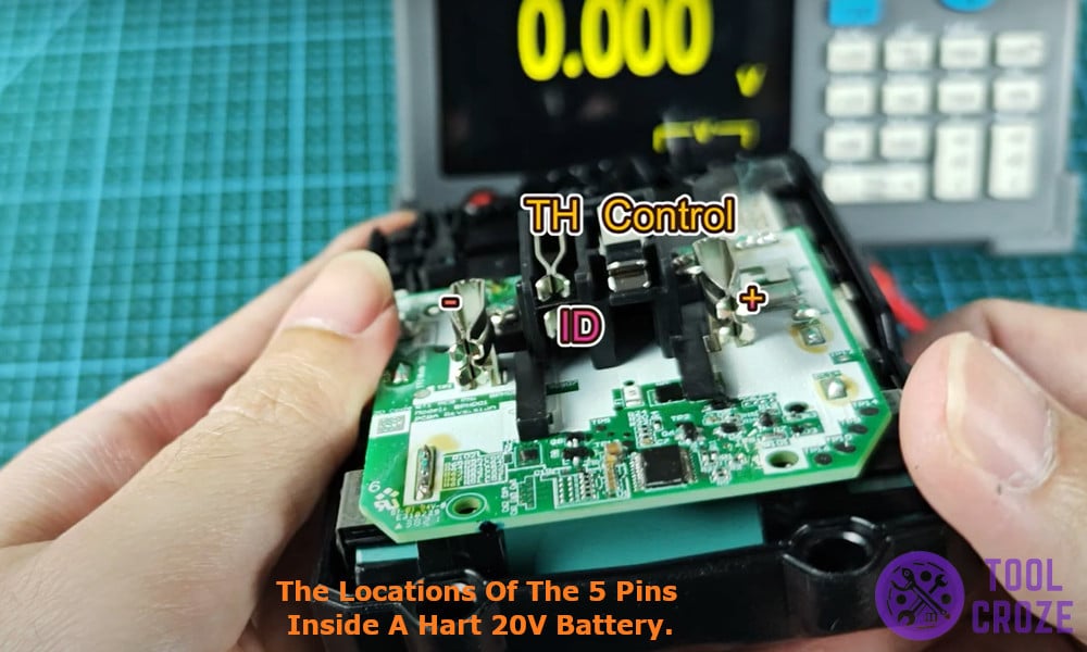
Then there was the ID pin which is mostly used for communication with the tool and lastly the Control (C) pin used for charger control and battery gatekeeping.
These pins not only indicated that the Hart battery is complicated to work with but also technologically advanced than the other batteries available in the market.
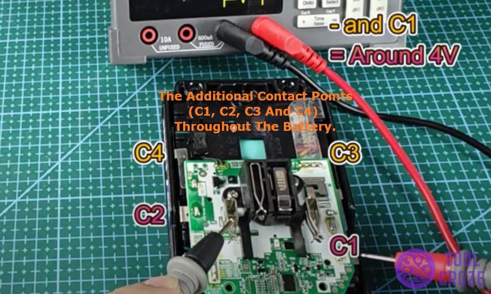
There were additional contact points throughout the battery which I named as C1, C2, C3, C4 in the pin out diagram.
These pins are used for balanced charging which is a way for smart chargers to tap into different points in the battery to monitor the voltage across individual cells inside the battery.
Related: HART Battery Not Charging: How to Reset
After this I grabbed my multimeter and set it to measure the voltage across each combination of pins on the battery and here are the readings.
- Positive to Negative – 20V
- Negative to TH – 0V
- Positive to TH – 20V
- Negative to ID – 0V
- Positive to ID – 20V
- Negative to C (Control) – 20V
- Positive to C – 0V
- Negative to C1 – 4V
- Negative to C2 – 8V
- Negative to C3 – 12V
- Negative to C4 – 16V
The Hart battery’s layout is a little more complex than some other batteries but the logic is pretty much the same.
As always be careful when working with high voltage batteries and make sure to use all the protective gears while opening and poking around a battery.
