On a random Tuesday I decided to do something a normal person doesn’t do. I took out my old Skil 20V battery and decided to test it out and create its pinout wiring diagram.
This battery helped me power my tools for the last two years and it seemed like a good way to honor it.
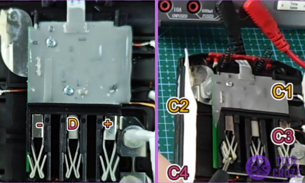
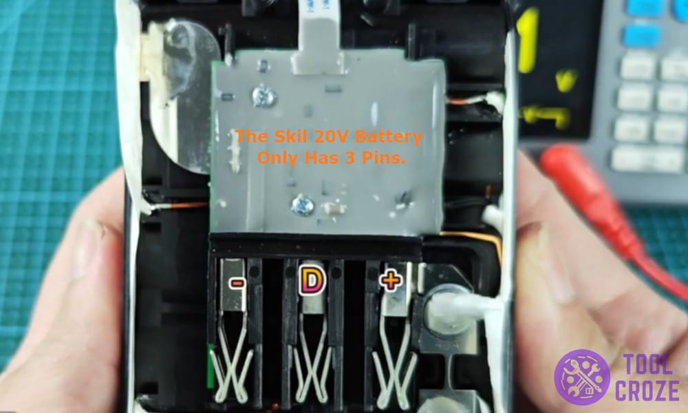
Once I opened it had only three pins, no complex separate thermistor, or control pins, just straight up negative, positive and data pins.
This is where things got more interesting and grabbed my multimeter to test it further.
But before you continue reading this article, you can watch first the short video I made about this topic. You can watch it below.
On the video, I showed the three pins and the four additional contact points inside a Skil 20V battery.
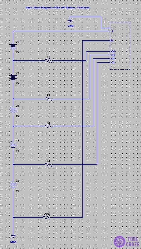
Pinout Wiring Diagram of a Skil 20V Battery
Here is what I found inside the Skil 20V battery to create its pinout diagram which can help you mod it, or even repair it when needed.
It’s very rare to see a very simple and less complex battery these days, especially a battery with three pins only.
I have tested a lot of batteries and most of them include 4 or more pins including temperature control pins or smart pins but the Skil battery begs to differ.
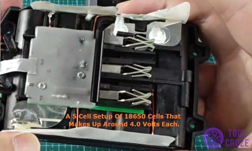
Once I opened the battery by removing its screws and removing its plastic cover I was greeted with a 5 cell setup of 18650 cells that makes up around 4.0 volts each.
Then, I started and identifying the pins using my multimeter and discovered that there were only three pins, positive (+) used as an main output pin, negative(-) used an ground pin, and a data(D) pin which is likely to be used as for communication between the battery and tool or the charger.
Now that I was sure of what these pins did it was time to test the voltages across each combination of pins.
It is important to know the voltages running across each pin as it can help me mod the battery to produce high power or repair it in future if it ever stops working.
Without giving it a further thought I picked up my multimeter again and went to work, and here are the readings that I measured.
- Positive – Negative – 20V
- Negative – D – 0V
- Positive – D – 20V
Surprisingly I also found 4 additional contact points in the battery packs which are marked as C1, C2, C3 and C4 respectively.
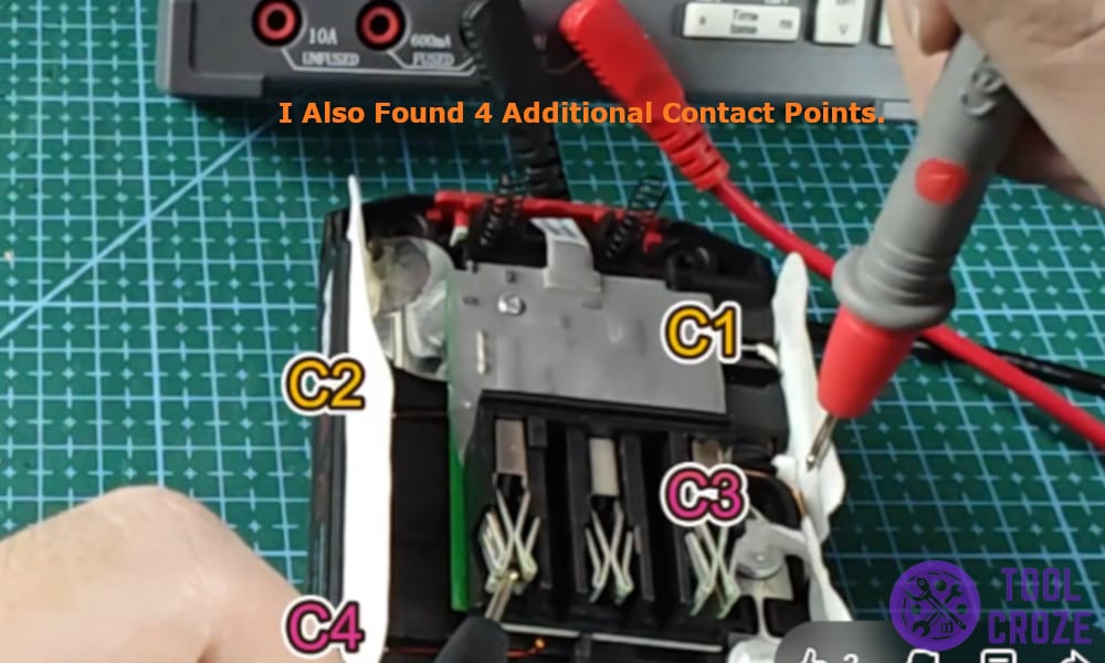
These contact points are used for balanced charging or smart charging to charge the battery equally and to make sure one single cell is not overcharged.
Related: How to Jumpstart a SKIL Battery Not Charging Flashing Red Light
Here are the readings that I recorded using an multimeter across the contact points on the Skil 20V battery.
- C1 – Negative – 4V
- C2 – Negative – 8V
- C3 – Negative – 12V
- C4 – Negative – 16V
