Pinout diagrams are pretty helpful when you’re working on a battery. They show users everything that’s going on inside the battery, from its wiring to how it all flows together.
Finding diagrams for specific batteries can be tough though. But, if you’re looking for a pinout diagram for a DeWALT 20v battery, you’re in luck, because that’s exactly what I’m here to focus on!
Pinout Diagram of a DeWALT 20v Battery
I’ll go over what’s inside the DeWALT 20v battery and other important details. First of all, though, I want to focus on the pinout diagram itself, which I’ll share below.
Pay close attention to the symbols. Even if you aren’t too sure about how to read diagrams like this, I’ll explain the symbols later so that it’s a lot easier for newer users to understand what’s what.
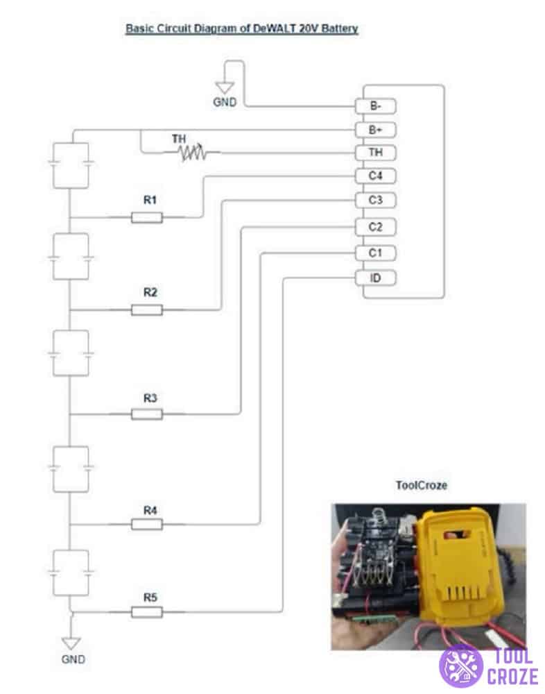
GND: This symbol in the diagram is what represents the “ground” inside of a DeWALT 20v battery.
Ground is the battery’s negative terminal (you need to know this when resetting the battery), which carries the electrical current to the original power source.
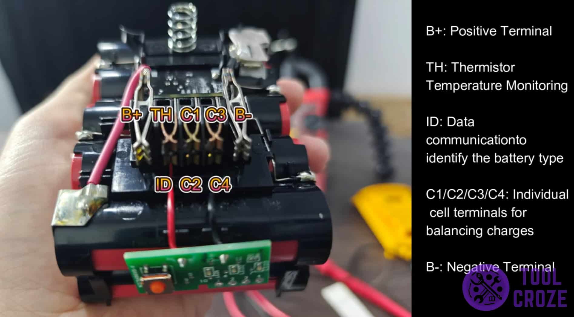
B-: This is the symbol that showcases the point for a negative battery connection.
B+: Similar to the last one, this one showcases the point for a positive battery connection.
C#: These symbols in the pinout diagram mark the locations of a capacitor.
Capacitors are a series of terminals that are used with B+ and B- to balance the battery’s charges. Each capacitor is assigned a number for identification purposes.
ID: The ID inside of a Milwaukee M18 battery refers to a serial number used to identify electrical components on a circuit board.
R#: The R symbol marks the location of resistors inside the battery.
Resistors regulate the electrical current to provide a specific voltage to the transistors. Similar to capacitors, they are named in a series starting from 1 (R1) to differentiate each across the board.
TH: This is the symbol that showcases where the thermistor on a DeWALT 20v battery is.
Thermistors are resistors that are dependent on temperature to function. They change resistance as temperature changes to maintain the ideal temperature for battery operation.
Single Cell Battery logo: This symbol doesn’t have letters associated with it. Instead, it has a logo of its own, which I’ll share with you in the image down here.
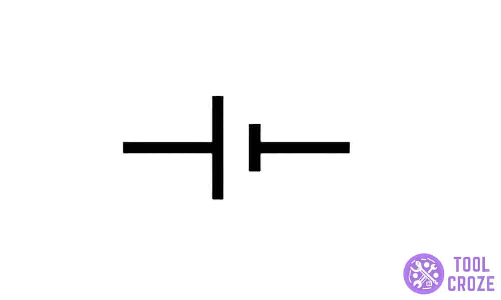
This represents where a single cell battery is on the pinout diagram from earlier. And that’s the last of it!
That’s all there is to cover about the pinout diagram for a DeWALT 20v battery. However, that ISN’T the end of it’s internal workings, which I’ll cover next.
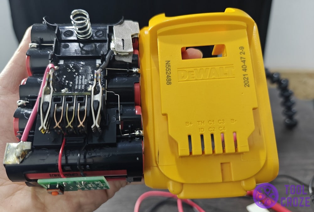
Inside The DeWALT 20v Battery Adapter
The battery holds a PCB circuit board with five resistors. Within it, the B- pin is tied to the C3 and C4 pins with R1 and R2.
The B+ pin is tied to R4 and R5. The TH pin is wired to the C and C2 pins. Each of these has its own function, and the battery would be dysfunctional without a single one.
Speaking of the circuit board, it’s also important to know about the voltages across it when working with the internal mechanisms of a battery. With that said…
Here are the voltages across specific parts of the circuit board:
- TH and B- = 20V
- ID and B- = 0V
- C1 and B- = 4V
- C2 and B- = 8V
- C3 and B- = 12V
- C4 and B- = 16V
- B+ and B- = 20V
