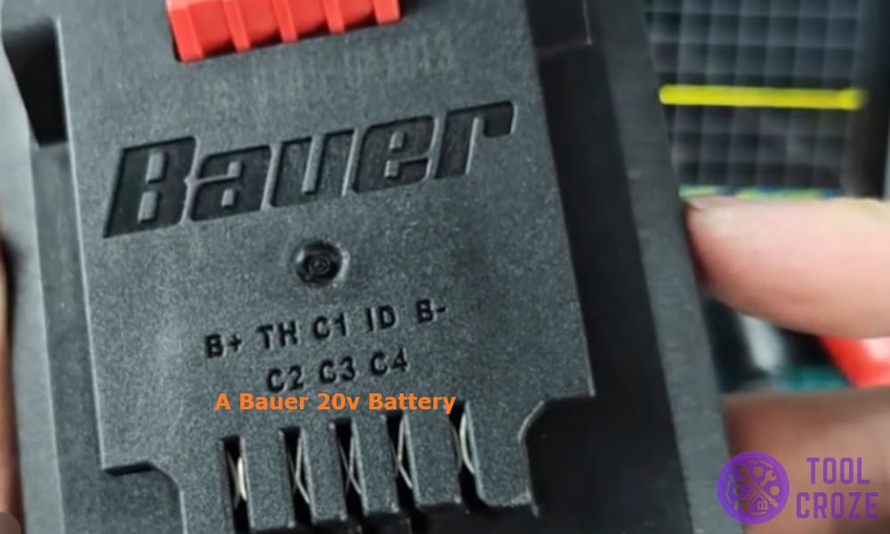
The Bauer 20V battery is very different from others and there is a reason to which I can say this with confidence.
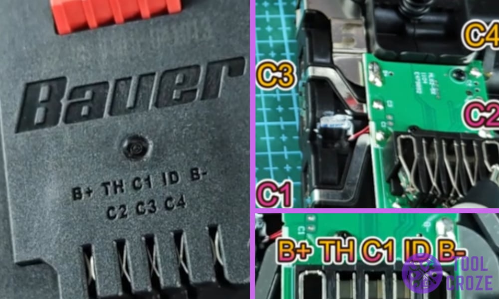
For starters the battery comes with 5 pins, unlike the other batteries available in the market the Bauer comes with 5 pins including a dedicated contact pin on the top to connect to chargers or power tools.
Not only that, I found many more interesting things on this battery that surprised me.
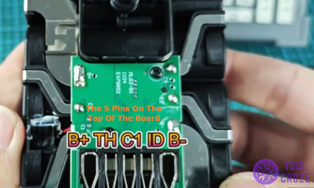
By the way, I also made a short YouTube video about this topic and you can watch it down below. On the video, I showed the 5 pins and 4 connector pins inside a Bauer 20V battery.
Pinout Wiring Diagram of a Bauer 20v Battery
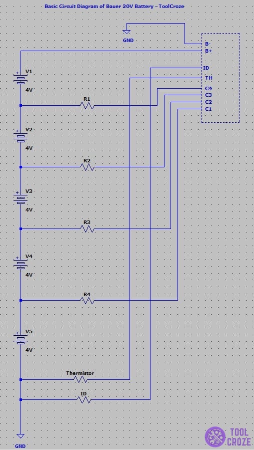
Here is a complete breakdown of the Bauer 20V battery and its pinout diagram to help you fix it or mod it in the future.
I couldn’t stop myself from grabbing the multimeter and poking each pin to see what voltage they provided, but before that I started by identifying each pin.
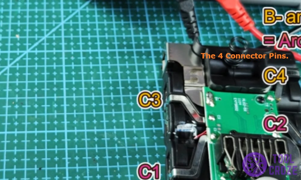
I was able to find 5 pins on the top of the board and 4 connector pins in total, each pin was used to perform a different task and served an important part.
The positive pin which was the left most pin on the battery worked as the main supply pin, it served the full 20V to the power tools using 5 lithium-ion cells connected in series each producing around 4V each.
Then there was the negative pin that was also connected to each connector pin(C1-C2), the negative pin worked as the ground in the battery and was used as a reference point to measure voltage while creating the pinout diagram.
The surprise came after I found the C1 pin as a dedicated pin, these pins are usually spread across the board of the battery and used as a charge tap pin but it has a dedicated slot on the Bauer 20V battery.
Then the usual ID pin which is used for tool or charger recognition was placed on the second last right pin, it is an important pin which signals if the battery is connected or not and then sends the power.
Related: How to Jumpstart a Bauer Battery Not Charging
Lastly there was the thermistor pin which is used to monitor the battery’s internal temperature and trigger the hot and cold delay function which acts as a safety measure.
Now that all the pins were identified it was time to measure the voltage across each combination of pins, and here are the results.
- Positive – Negative – 20V
- Negative – TH – 0V
- Positive – TH – 20V
- Negative – ID – 0V
- Positive – ID – 20V
- Negative – C1 – 4V
- Negative – C2 – 8V
- Negative – C3 – 12V
- Negative – C4 – 16V
