The Milwaukee M18 battery is a 18V power tool battery that has helped me in various situations. As a DIY excerpt and a person that is curious 24×7 I took on a task to figure out the wiring inside the battery.
While I thought it would be an easy task it was not and I was blown away by the wiring and the complex design of the Milwaukee M18 battery.
But before you continue reading this article, you may first watch the short video I made about this topic. You can watch it below.
In the video, I opened my Milwaukee M18 battery and tested all the contact points inside using a multimeter.
But I did not give up and drew a simple pinout wiring diagram for anyone who wants to fix their dead battery to mod it to provide them even more power. Here is what I found.
Pinout Wiring Diagram of a Milwaukee M18 Battery

I started with collecting the important tools, a multimeter that would help me test the voltages across the pins and some prying tools to open the battery up.
I used my old Milwaukee battery which I had been using for the last 2 years and I knew it was losing power so it became a good test mule.
Related: Reset Milwaukee M18 Battery Without Charger: 3 Ways I Recommend
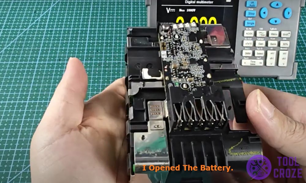
I opened the battery and I was surprised to see 5 pins, most of the batteries use a 3 pin setup but the Milwaukee seemed to have a more complex setup.
Here are all the pins that I found, positive and negative pins that supplied power to the tools.
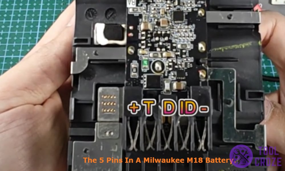
Then there was the temperature (T) pin that monitored the battery’s internal temperature and signaled the battery charger to stop charging in case of unsuitable temperature.
Data marked as D in the pinout diagram is the pin used to send battery status to the tools or chargers, this pin is used to measure battery charging level or share internal codes to power tools.
Lastly it has the identification / Sense (ID) pin that ensured compatibility with Milwaukee tools.
Related: 4 Common Milwaukee M18 Battery Problems
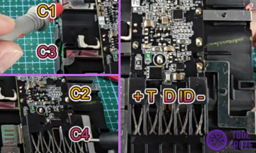
I also found additional contact points which I named as C1, C2, C3, C4 in the diagram to refer to them.
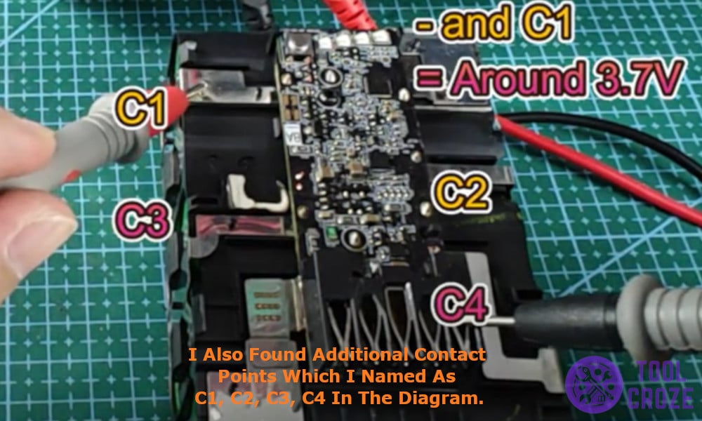
These pins are used to smartly track the internal voltage of the battery and used for balanced charging which is a way for smart chargers to tap into different points and make sure the battery is healthy and is charging normally.
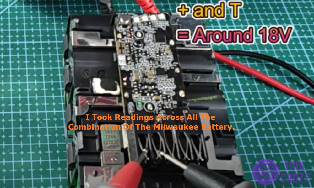
Then I grabbed my multimeter and took readings across all the combination of the Milwaukee battery and here were the results –
- Positive – Negative – 18V
- Negative – T (Temp) – 0V
- Positive – T – 18V
- Negative – D (Data) – 18V
- Positive – D – 0V
- Negative – ID – 18V
- Positive – ID – 0V
- Negative – C1 – 3.6V
- Negative – C2 – 7.2V
- Negative – C3 – 10.8V
- Negative – C4 – 14.4V
While the Milwaukee battery seems to be really complex it gets easier once you map it out. The battery is pretty simple and straightforward, make sure to check your measurements and avoid shorting anything or damaging the battery if you want to mod it.
