🔌 Inductor Wire Gauge Calculator
Find the correct AWG wire size for your coil — enter current, turns, and core dimensions for instant recommendations
| AWG | Diameter (mm) | Diameter (in) | Cross-section (mm²) | Max Current (A) | DC Resist (Ω/m) | Skin Depth 100kHz |
|---|---|---|---|---|---|---|
| 10 | 2.588 | 0.1019 | 5.261 | 15.0 | 0.00328 | Use Litz |
| 12 | 2.053 | 0.0808 | 3.310 | 9.3 | 0.00521 | Use Litz |
| 14 | 1.628 | 0.0641 | 2.081 | 5.9 | 0.00828 | Use Litz |
| 16 | 1.291 | 0.0508 | 1.309 | 3.7 | 0.01313 | Marginal |
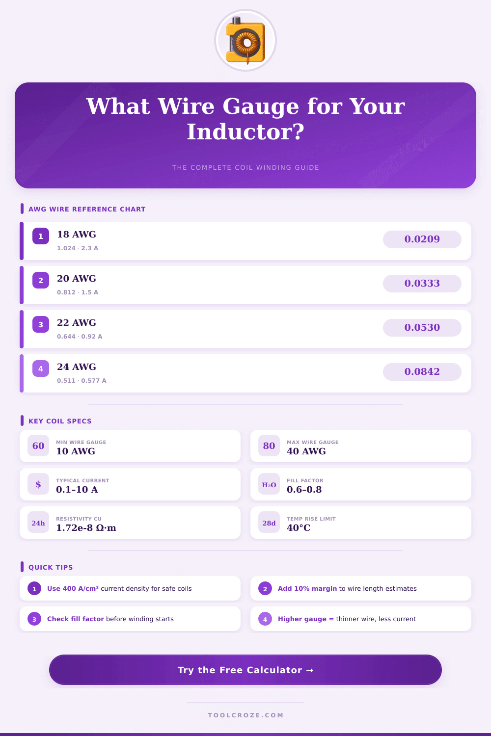
| 18 | 1.024 | 0.0403 | 0.8231 | 2.3 | 0.02090 | OK <20kHz |
| 20 | 0.8128 | 0.0320 | 0.5189 | 1.5 | 0.03326 | OK <50kHz |
| 22 | 0.6438 | 0.0253 | 0.3255 | 0.92 | 0.05295 | Good |
| 24 | 0.5106 | 0.0201 | 0.2047 | 0.577 | 0.08417 | Good |
| 26 | 0.4049 | 0.0159 | 0.1288 | 0.361 | 0.1338 | Excellent |
| 28 | 0.3211 | 0.0126 | 0.08098 | 0.226 | 0.2127 | Excellent |
| 30 | 0.2546 | 0.0100 | 0.05093 | 0.142 | 0.3382 | Excellent |
| 32 | 0.2019 | 0.0079 | 0.03203 | 0.091 | 0.5380 | Excellent |
| 34 | 0.1601 | 0.0063 | 0.02012 | 0.057 | 0.8557 | Excellent |
| 36 | 0.1270 | 0.0050 | 0.01267 | 0.035 | 1.3610 | Excellent |
| 38 | 0.1007 | 0.0040 | 0.007967 | 0.022 | 2.1640 | Excellent |
| 40 | 0.07987 | 0.0031 | 0.005010 | 0.014 | 3.4410 | Excellent |
| Material | Resistivity (μΩ·cm) | Conductivity vs Cu | Density (g/cm²) | Skin Depth 100kHz | Best Application |
|---|---|---|---|---|---|
| Copper (Cu) | 1.72 | 100% | 8.96 | 0.21 mm | All inductors |
| Silver-Plated Cu | 1.59 | 108% | 9.00 | 0.20 mm | RF, high-Q coils |
| Aluminum (Al) | 2.82 | 61% | 2.70 | 0.27 mm | Light-weight coils |
| Litz Wire | 1.72* | ~95%* | 8.90 | N/A | HF, >10kHz |
| CCA Wire | 2.50 | 69% | 4.50 | 0.25 mm | Cost-reduced designs |
| Frequency | Skin Depth Cu (mm) | Max Solid Wire Dia | Recommended AWG | Litz Recommended? |
|---|---|---|---|---|
| 50 Hz | 9.38 | 18.76 mm | 6 AWG or larger | No |
| 1 kHz | 2.10 | 4.20 mm | 10–12 AWG | No |
| 10 kHz | 0.66 | 1.32 mm | 16–18 AWG | Consider |
| 50 kHz | 0.30 | 0.60 mm | 22–24 AWG | Recommended |
| 100 kHz | 0.21 | 0.42 mm | 24–26 AWG | Yes |
| 500 kHz | 0.094 | 0.19 mm | 32–34 AWG | Yes |
| 1 MHz | 0.066 | 0.13 mm | 36–38 AWG | Yes |
| Application | Inductance | Frequency | Typical Current | Recommended AWG | Wire Type |
|---|---|---|---|---|---|
| SMPS Boost 5V→12V | 10–100 μH | 50–500 kHz | 1–5 A | 22–26 AWG | Litz or solid |
| Buck Converter | 10–47 μH | 100–400 kHz | 1–10 A | 18–24 AWG | Litz recommended |
| Audio Crossover | 0.5–5 mH | 1–20 kHz | 1–4 A | 18–22 AWG | Copper magnet |
| Power Filter Choke | 1–50 mH | 50/60 Hz | 1–20 A | 12–18 AWG | Copper magnet |
| RF Tank Coil | 1–50 μH | 1–30 MHz | <1 A | 22–30 AWG | Silver-plated |
| Tesla Coil Primary | 10–50 μH | 50–500 kHz | 100–500 A | 6–10 AWG | Copper strap |
| Motor Drive Choke | 0.5–5 mH | 5–20 kHz | 5–50 A | 10–16 AWG | Copper magnet |
| LED Driver | 22–100 μH | 200–500 kHz | 0.3–2 A | 26–30 AWG | Litz or solid |
Wires of different ratings matter more than one usually thinks, especially during building of inductor wire. That affects the resistance, the ability to handle power and, believe it or no, even the performance in audio uses. If one misses this, one risks failed result or spending money for something that does not work properly.
Here the main point about wire ratings and inductance: the tie is not direct, but it however exists clearly. The thickness of the wire decides how many turns one can well arrange on a defined core, and because the inductance depends strongly on the number of turns, the rating ultimately plays a role quite big, although it is not the main element. For a single turn, the same inductance genuinely depends on the diameter of the wire itself.
Why Wire Size Matters for Inductors and Audio
When one has a spool with many turns, each of them has its own inductance according to the wire thickness, except the mutual inductance from all other turns that is assembled around it.
The factor of quality, that folks call Q, binds directly to the rating also. Q simply is the inductance divided by the resistance, what seems easy until one understands the results. Good rating for inductor wire can reach the same inductance as fatter wire, but it brings bigger resistance for DC.
This is trouble, because it requires thinnre wires for less efficient inductor wire everywhere. For steady inductance and frequency, growing the diameter of the wire can raise the value of Q.
In work with audio crossovers, choosing the right rating genuinely matters. Thicker wire causes fewer losses during supply of power to a woofer, what indeed gives more energy to it. Here said, and this deserves too note; the difference between 20 and 18 ratings is entirely little.
Most listeners simply will not notice it. The main target stays to reach the wanted inductance and values of DC-resistance. A bit higher resistance for DC occasionally helps, according to the way the crossover is laid.
Some met this precise case, when one required an inductor wire of 0.35 mH in 20 AWG for a draft of crossover, but only had a version of 22 AWG. Such replacement happens always in homemade buildings.
For circuits with power, the size of the cable depends on the ability to handle current. At 100 watts in a system of 50 ohms, one finds roughly 1.41 amps flowing through the inductor wire. Wire of 26 AWG can last that without big sweating…
It is rated for around 2 amps, especially if one has only some turns. With inductor wire of dollar converters working in 500 kHz, the skin effect starts to matter, likewise as in designs of flyback. The rating of wire that must last 20 amps depends on the reasonable rise of temperature, so there is not one single answer.
Tools for design of inductor wire can help specify it, and genuinely, AC-effects as skin effect commonly go insecond plan compared with attention to the cross section area.
When one replaces defective inductor wire, one should keep the rating of the wire roughly the same, it was chosen initially for a certain level of current, at the end of everything.