🔧 Air Compressor Pipe Size Calculator
Calculate the correct pipe diameter for your compressed air system — minimize pressure drop & maximize flow efficiency
| Nominal Pipe Size | Inner Diameter (in) | Max CFM @ 100 PSI | Max CFM @ 125 PSI | Max Velocity (ft/s) | Sch. 40 Max PSI |
|---|---|---|---|---|---|
| 1/4 in | 0.364 | 5 | 6 | 30 | 580 |
| 3/8 in | 0.493 | 10 | 12 | 30 | 520 |
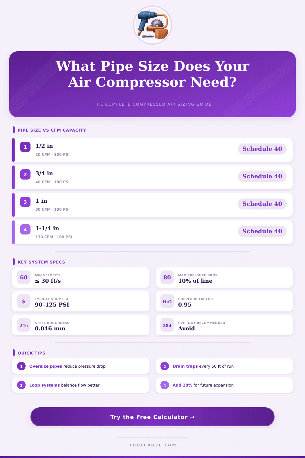
| 1/2 in | 0.622 | 20 | 25 | 30 | 480 |
| 3/4 in | 0.824 | 40 | 50 | 30 | 450 |
| 1 in | 1.049 | 80 | 100 | 30 | 450 |
| 1-1/4 in | 1.380 | 130 | 160 | 30 | 370 |
| 1-1/2 in | 1.610 | 200 | 250 | 30 | 330 |
| 2 in | 2.067 | 340 | 425 | 30 | 280 |
| 2-1/2 in | 2.469 | 500 | 625 | 30 | 250 |
| 3 in | 3.068 | 800 | 1000 | 30 | 230 |
| Tool / Application | CFM Required | Operating PSI | Min Pipe Size | Duty Cycle |
|---|---|---|---|---|
| Brad Nailer | 0.3 – 1 | 70 – 120 | 3/8 in | Intermittent |
| Framing Nailer | 2 – 4 | 100 – 120 | 1/2 in | Intermittent |
| Impact Wrench (1/2 in) | 4 – 6 | 90 – 120 | 1/2 in | Intermittent |
| Die Grinder | 4 – 8 | 90 – 100 | 1/2 in | Continuous |
| Orbital Sander | 6 – 9 | 90 – 100 | 3/4 in | Continuous |
| HVLP Spray Gun | 7 – 12 | 29 – 50 | 3/4 in | Continuous |
| Air Ratchet | 3 – 5 | 90 – 100 | 1/2 in | Intermittent |
| Sandblast Pot (small) | 10 – 25 | 80 – 100 | 3/4 in | Continuous |
| Plasma Cutter Air | 4 – 8 | 70 – 120 | 1/2 in | Continuous |
| Pneumatic Conveying | 50 – 200 | 15 – 90 | 1-1/2 in | Continuous |
| Fitting Type | 1/2 in Pipe (ft) | 3/4 in Pipe (ft) | 1 in Pipe (ft) | 1-1/2 in Pipe (ft) | 2 in Pipe (ft) |
|---|---|---|---|---|---|
| 90° Standard Elbow | 2.0 | 2.5 | 3.0 | 4.0 | 5.5 |
| 45° Elbow | 0.8 | 1.1 | 1.3 | 1.8 | 2.4 |
| Tee (run) | 0.5 | 0.7 | 0.9 | 1.2 | 1.6 |
| Tee (branch) | 3.0 | 4.0 | 5.0 | 6.5 | 9.0 |
| Gate Valve (open) | 0.3 | 0.4 | 0.5 | 0.7 | 1.0 |
| Ball Valve (open) | 0.2 | 0.3 | 0.4 | 0.5 | 0.7 |
| Globe Valve (open) | 12.0 | 15.0 | 18.0 | 24.0 | 32.0 |
| Check Valve (swing) | 5.0 | 7.0 | 9.0 | 12.0 | 16.0 |
| Shop Type | Compressor Size | Typical CFM | Recommended Main Pipe | Drop Lines |
|---|---|---|---|---|
| Home Garage (1 tool) | 1–3 HP | 3–8 CFM | 1/2 in | 3/8 in |
| Small Auto Shop (2 bays) | 5 HP / 20 gal | 15–25 CFM | 3/4 in | 1/2 in |
| Medium Auto Shop (4 bays) | 10 HP / 80 gal | 40–60 CFM | 1 in | 1/2 in |
| Woodworking Shop | 3–5 HP | 10–20 CFM | 3/4 in | 1/2 in |
| Metal Fabrication Shop | 10–25 HP | 50–100 CFM | 1-1/4 in | 3/4 in |
| Industrial / Production | 50+ HP | 200+ CFM | 2 in+ | 1 in |
Election of the right size for the tubes in an air compressor setup is more important than many folks think. The packed air flows from the air compressor to the air devices and work spots through the pipe. Truth, a pipe simply is a tube, but choosing the right type and size truly helps to reach the best results.
A well planned setup did not lose more than 1 psi of pressure in a 100 psi system. If the pressure losses pass 3 percent, that already is too much. Sometimes big pressure drop in the channel is solved by simply raising the working pressure at the air compressor, for example from 7 bars to 8 bars.
Choose the Right Pipe Size for Your Air Compressor
Even so, that is not the most efficient way. Too commonly one settles this problem only by raising the air compressor, what wastes energy.
The most common 60-gallon air compressors have at least half-inch NPT outlet. When the outlet at the air compressor is 1-inch, then using pipe of that size could make sense, but it probably is not needed. In home or small workshop systems, 3/4-inch or 1-inch pipe works quite well as main line.
For distanecs more than 150 feet, 3/4-inch pipe is a good choice. A bigger pipe size will lower the pressure loss because of friction, but it is not always worth the cost for the particular setup.
Here is one thing that folks commonly miss. The fixtures are just as important as the pipe size. If you run a half-inch air line, but use fast connectors with only 1/4-inch holes, that simply cancels the advantage of the thicker pipe.
The fixtures must match the pipe size, otherwise the narrowest part becomes the main restriction. Tools with high volume will fail on a small line even if the pressure in the tank seems good.
Always aim to expand the intake pipe one or two sizes above the size of the air compressor connector. For lengths more than 50 feet, one advises to use pipe at least one grade bigger than the connection at the filter. The main line can have bigger diameter, while the side branches from it can be a bit more small.
For the airflow in the tubes, the ideal is up too 20 feet each second with little turbulence. Up to 30 feet each second yet works as a limit in industrial uses. The pipe size one chooses according to the whole length of the pipe and the whole involved flow.
Different materials work for the piping. Some use copper, other black iron pipe, or aluminum systems with plastic screw fixtures. Aluminum pipe in 8-foot sections installs more cleanly than rolled pipe, that one must straighten.
A short bit of flexible pipe between the air compressor and themain line parts helps to isolate vibrations.