As an electronic crackhead, I love finding out how much juice or voltage these batteries produce. Every time I buy a new battery I cannot resist pulling it apart and finding out what exactly is going on inside the battery.
This is what happened when I bought a pair of Hercules 20V batteries and opened one to find out what was happening inside of it and spoiler alert this is not an ordinary battery like others.
I started probing each pin to measure its voltage and to create a pinout diagram of the battery to help me fix it in the future or understand the battery in depth. Here is what I found, and how it all works.
I also made a short video about this topic and you can watch it below.
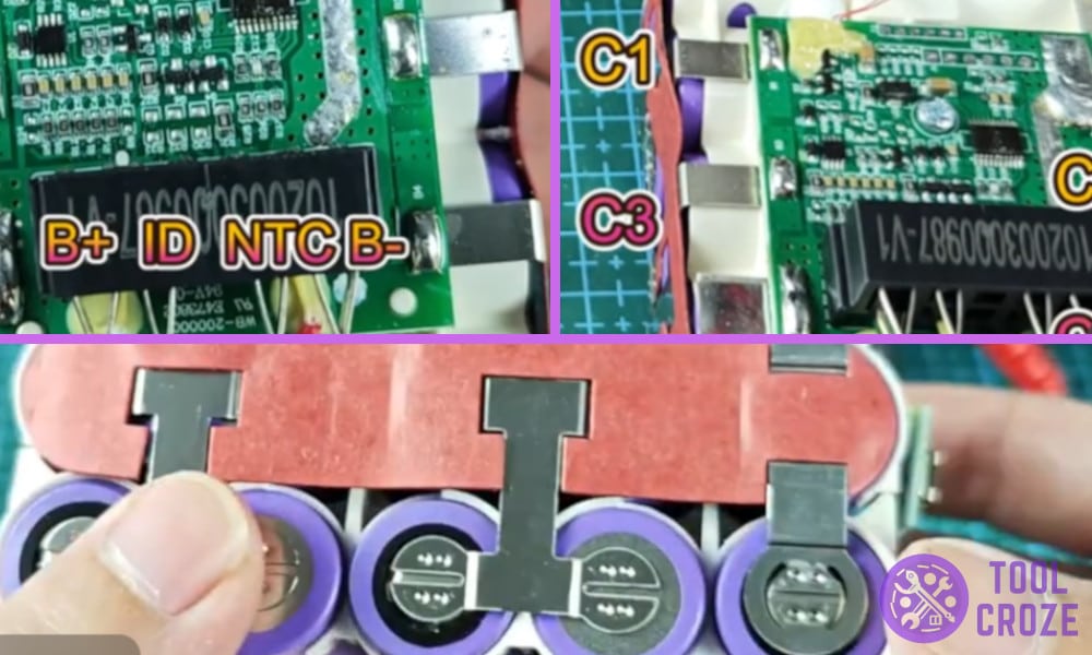
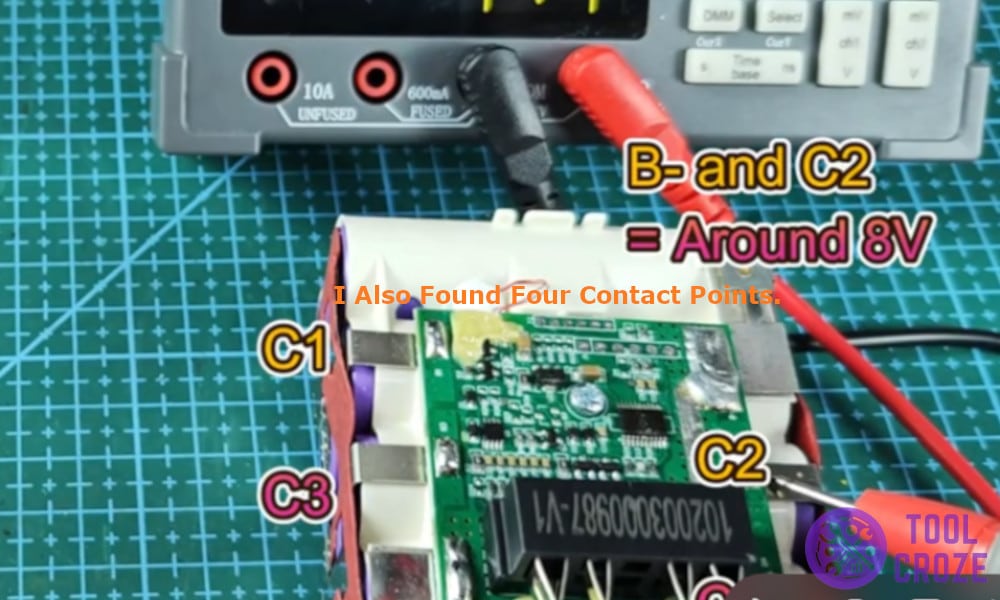
In the video, I showed the four contact points inside a Hercules 20V battery: Positive – B+, ID – for tool, NTC (thermistor) – for temperature monitor, and Negative – B-. There are also four additional contact points which I referred to as C1, C2, C3 and C4.
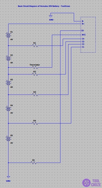
Pinout Wiring Diagram of a Hercules 20v Battery
This battery was not even an hour old when I started opening it.
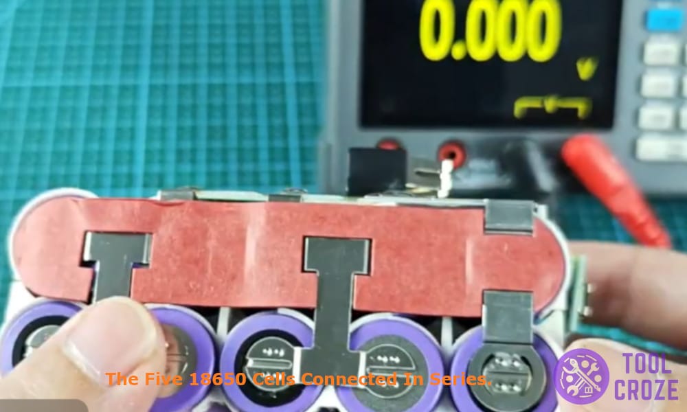
I removed the plastic cover that held the battery pack inside to get better access and the very first thing I saw were the five 18650 cells connected in series to output the 20V that the Hercules battery provides.
These cells produce around 4V each to give the battery a powerful backup and run the power tools. Then I picked up my multimeter and went on the hunt to find the individual pins.
First was the Positive pin which is marked as B+ in the diagram, this is the main pain used to supply power to the power tool, then it was the Negative pin marked as B-, it acts as the ground pin for the battery pack.
An ID pin which is used to communicate between the battery and the tool or charger is a common pin found in most of the batteries, it acts as an important pin in the battery without which a battery may not charge.
Lastly there was the thermistor pin (NTC) which I saw for the first time.
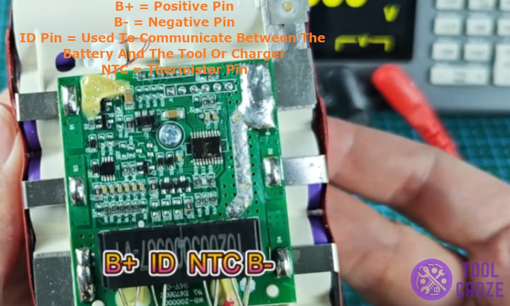
It connects the temperature sensor inside the battery which is used to monitor the internal temperature of the battery and ensure the hot and cold delay safety feature works properly to prevent any damage to the battery.
I also found four contact points which I marked as C1, C2, C3 and C4 respectively in the pinout diagram. They are used to implement balanced charging and make sure that one individual cell is not overcharged.
Once every pin was identified, there was only one thing left to do for me and that was to measure the voltage across each individual pin and here are the readings.
- Positive – Negative – 20V
- Negative – NTC – 12V
- Positive – NTC – 8V
- Negative – ID – 0V
- Positive – ID – 20V
- Negative – C1 – 4V
- Negative – C2 – 8V
- Negative – C3 – 12V
- Negative – C4 – 16V
