⚙ Worm Gear Pitch Calculator
Calculate gear ratio, lead angle, efficiency, output RPM, and center distance for worm gear sets.
📐 Full Calculation Breakdown
High load
Industrial standard
Medium load
General purpose
Light load
Low-noise apps
Very light load
Occasional use only
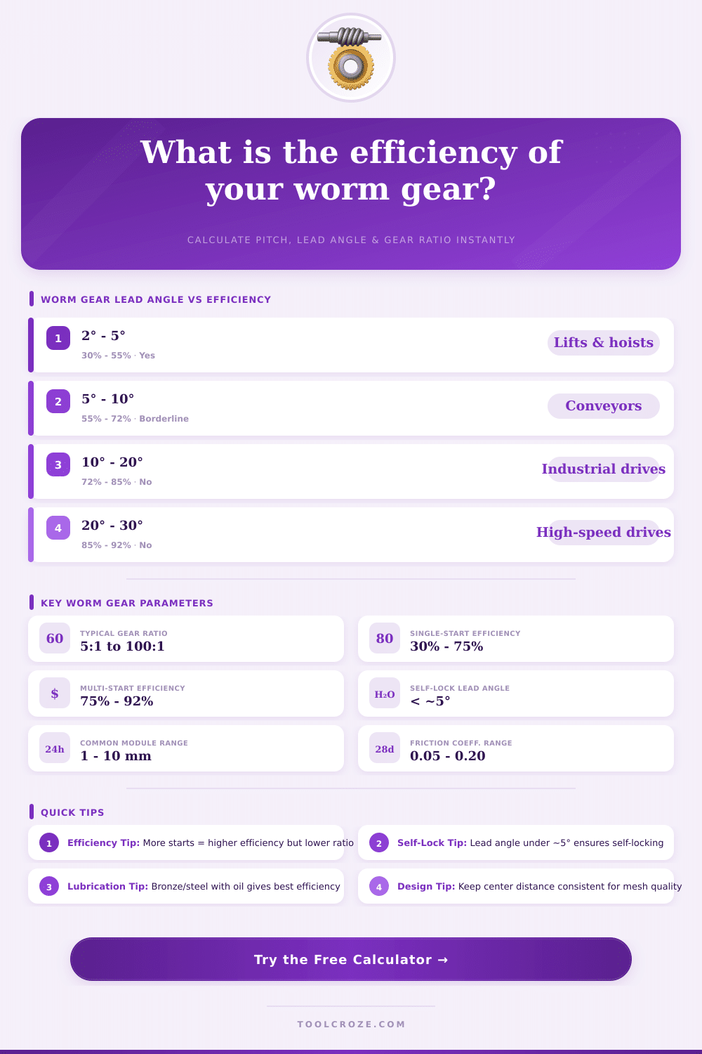
| Lead Angle | Efficiency (Bronze/Steel) | Self-Locking | Typical Application |
|---|---|---|---|
| 2° – 4° | 30% – 50% | Yes | Hoists, lifts, door operators |
| 4° – 8° | 50% – 65% | Marginal | Conveyors, single-start drives |
| 8° – 14° | 65% – 78% | No | General industrial gearboxes |
| 14° – 20° | 78% – 86% | No | Double/triple-start drives |
| 20° – 30° | 86% – 92% | No | High-speed multi-start drives |
| Starts | Gear Ratio Example | Efficiency Range | Typical Speed / Use |
|---|---|---|---|
| 1 (Single) | 20:1 – 100:1 | 30% – 75% | Low speed, high reduction, often self-locking |
| 2 (Double) | 10:1 – 50:1 | 60% – 82% | Medium speed, balanced efficiency |
| 3 (Triple) | 5:1 – 30:1 | 70% – 87% | Higher speed, lower ratio, actuators |
| 4 (Quadruple) | 5:1 – 20:1 | 75% – 92% | High speed, compact high-speed drives |
| Module (mm) | Worm PD Range (mm) | Wheel Teeth Range | Typical Application |
|---|---|---|---|
| 1 | 10 – 20 | 20 – 60 | Instruments, small drives |
| 2 | 16 – 35 | 20 – 80 | Light duty, office equipment |
| 3 | 22 – 50 | 24 – 100 | General purpose conveyor |
| 4 | 28 – 70 | 28 – 80 | Industrial gearboxes |
| 5 | 35 – 90 | 30 – 80 | Medium-duty machinery |
| 8 – 10 | 60 – 140 | 30 – 60 | Heavy-duty, lifting equipment |
The pitch of worm gear ranks between those themes that seems hard, but truly simple, when one grasps the basics. One finds the axial pitch of the worm, measuring the gap between same spots on next threads, that runs parallel to the axis. Seriously note, that the axial pitch of the gear matches the circular pitch of the worm gear, with that it meshes.
Worm gears sort into two main types: fine pitch and coarse pitch. Fine pitch worms and gears are used mainly for passing on motion, linear or turning, instead of for passing on power or torque. One must think about those points, when one chooses the right modle for a particular job.
What Is Worm Gear Pitch
In the metric system one describes the size of each tooth by means of the module. The bigger the module, the bigger the gear teeth become. In the imperial system one calls the pitch of worm gear diametral pitch.
It outlines the amount of teeth for one inch of working diameter. Like this, a 24-tooth gear with 12 diametral pitch would have a working diameter of 2 inches. A worm with around 4 teeth per inch would probably have 12 diametral pitch, what results in about 0.2618 inches between teeth on the worm.
There are also some useful formulas. The normal pitch is equal too the axial pitch times the cosine of the lead angle. The lead of worm gears is the axial pitch times the number of starts or threads.
The lead shows the distance, that one thread moves during one turn. One can count the circular pitch, sharing pi by the diametral pitch.
The diametral pitch of the gear matches that of the worm. The pitch of the worm itself comes from the lead at the pitch line, much like with regular gears. The profile shape of teeth on the gear is curved, with the center sitting closer to the base than the outer edge, because it must match the form of the worm.
An interesting fact is, that a change of diametral pitch affects the balance between strength and durability in the design of gears. Strength relates to resistance against tooth wear, while durability concerns contact pressure and resistance against surface damage. When one shapes a worm by means of crowning, one can alter the contact angle and pitch, without touching the pitch line parallel to the axis.
To raise the contact angle one needs to expand the axial pitch to a new amount.
There is also a double worm gear, that stores a worm with varying pitch. That build allows to closely match the meshing with the worm, removing any play between them. Usually one needs to know details like outer diameter, number of leads, helix angle, central distance andpitch, when one works with worm gears, because they commonly do overlap.