Crimp Calculator
Estimate conductor area, strand area, barrel fill, crimp height fit, compression ratio, pull force, and insulation OD support for wire terminal crimps.
Use a named sample to load realistic conductor, terminal barrel, crimp height, and insulation dimensions, then tune the values to your terminal drawing.
Crimp Breakdown
| Wire Gauge | Area mm² | Typical Barrel ID | Sample Pull Guide |
|---|---|---|---|
| 24 AWG | 0.205 | 0.80 to 1.00 mm | 12 to 18 N |
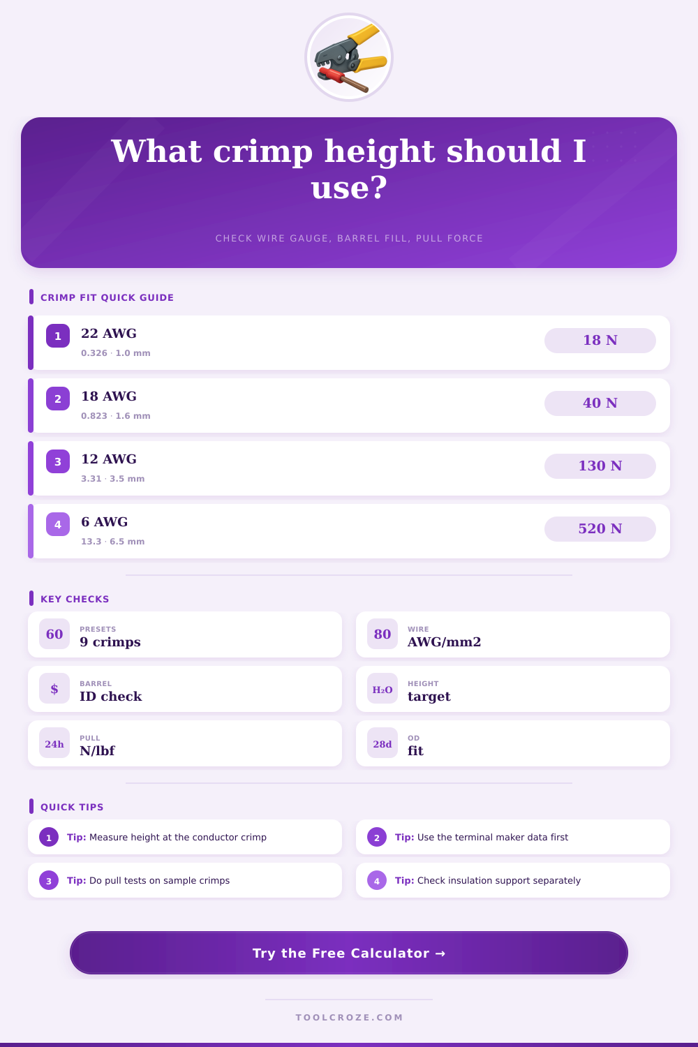
| 22 AWG | 0.326 | 0.90 to 1.20 mm | 18 to 28 N |
| 20 AWG | 0.518 | 1.10 to 1.40 mm | 28 to 38 N |
| 18 AWG | 0.823 | 1.40 to 1.80 mm | 40 to 60 N |
| 16 AWG | 1.31 | 1.80 to 2.30 mm | 60 to 90 N |
| 14 AWG | 2.08 | 2.30 to 3.00 mm | 90 to 130 N |
| 12 AWG | 3.31 | 3.20 to 4.00 mm | 130 to 180 N |
| 10 AWG | 5.26 | 4.20 to 5.20 mm | 220 to 310 N |
| Barrel Style | Fill Target | Compression Target | Height Check |
|---|---|---|---|
| Open barrel F-crimp | 35% to 60% | 75% to 92% | Wing curl touches strands |
| Closed barrel terminal | 35% to 55% | 70% to 90% | No flash, no loose wire |
| Insulated terminal | 30% to 50% | 65% to 85% | Insulation not cut |
| Butt splice sleeve | 35% to 58% | 70% to 90% | Centered wire stop |
| Tubular cable lug | 40% to 65% | 72% to 92% | Full die imprint |
| Check | Low Reading | High Reading | Shop Action |
|---|---|---|---|
| Compression ratio | Loose strands | Cut strands | Adjust die height |
| Barrel fill | Wrong terminal | Wire too large | Change barrel size |
| Pull force | Weak grip | May neck wire | Run pull samples |
| Insulation OD | No support | Jacket crushed | Use correct rear crimp |
A crimp are formed when a wire and a terminal are forced together. For a crimp to be successful, the strand of the wire should deform enough to permit electrical contact between the wire and terminal, but the crimp should not crush or cut the strands of the wire. If a person creates an incorrect crimp, the results will most likely be high resistance or signals that interrupts the circuit.
The calculator remove the need for a person to guess at or to read from printed charts that provide value for electrical parameters for different wires and terminals. The conductor area of the wire after the insulation is stripped is the most important of the wire parameter. Finely stranded wires often have a larger conductor area than the American Wire Gauge (AWG) table suggest for that gauge of wire.
How to Check Wire Crimps
Conversely, stiff single strand wires often have a smaller conductor area than the AWG table suggests. Fields for entering the strand count and the diameter of each strand allow a person to enter the conductor area to ensure it match the wire being used. If the calculated area of the conductor is outside of the printed AWG gauge by more than a few percent, the conductor should be measured with a micrometer to ensure accuracy in determining the conductor area.
Barrel fill is important in that the inside diameter of the terminal barrel is a fixed dimension. If there is too little barrel fill, the wire strands will rattle within the terminal. If there is too much barrel fill, the metal will not have any room to move within the crimped terminal.
The calculator allows a person to verify that the area of the wire is appropriate for the terminal barrel. Open barrel F crimps can have a broader range of barrel fill than closed barrel crimps. For insulated terminals, the barrel fill calculation is more critical than for uninsulated terminal, as the insulation will add to the constraint on the terminal.
Crimp height is one of the parameter that should be measured. The crimp height should be measured across the portion of the crimp that conducts electricity, not across the portion that support the insulation. The target crimp height can be calculated from the diameter of the terminal barrel, the thickness of the terminal wall, the area of the wire, and the width of the crimp.
If the measured crimp height falls outside of the calculated target, the die should be adjusted. Unlike pull force, crimp height can be easily measured with a micrometer, though measuring crimp height take time. The compression ratio of a crimp is calculated from the area of the conductor divided by the area of the crimp cavity, which is calculated from the crimp height and the crimp width.
The compression ratio indicate how compact the strands of wire are within the crimp. If the compression ratio is below the lower target, the strands of wire within the crimp are too loose. If the ratio is above the upper target, the strands may have been shaved during the crimping process, or the plating on the terminal may be cracked.
Pull force is calculated from the same parameter as the other electrical parameters. However, it is necessary to test the terminals and wires under production conditions using calibrated equipment to determine actual pull force. The calculated pull force is the force at which the wire should be pulled.
If the calculated force is much lower than the pull force published for the terminals, the wire and terminals is a marginal combination. The insulation support for a terminal grip the insulation of the wire. It must have enough clearance to open without cutting the insulation, yet it must be strong enough to support the wire against flexing.
The outer diameter of the insulation should be entered into the calculator along with the opening of the insulation support within the terminal. The calculator will indicate whether the support for the insulation is within an acceptable range. If it is not, the rear die should be adjusted independently of the crimped conductor.
The reference tables include the inside diameter of the terminal barrels and the pull forces for various AWG size. These tables can help to determine if the wire and terminals are within the common range. The tables are not a replacement for the terminal drawings, but can help to indicate if the crimp is outside the normal range.
Many people commit a few common error when crimping wires and terminals. For instance, many people select the size of the terminal barrel for the insulation, not for the conductor. Additionally, the same die height is used for both fine stranded wires and stiff single strand wires.
Other common errors are measuring the crimp height incorrect or not performing an insulation support check. The best use of this calculator is as a planning tool. The wire and terminal data should be entered.
The various parameter should be reviewed, and a small batch of the wire and terminals should be built. The crimp height should be measured and pull tests performed. For critical application, the cross section of the crimp should be inspected with a microscope.
If the measured parameter match those calculated with the tool, the wire and terminals can be used in the project. If the two set of measurements do not match, the parameters must be reviewed and the crimped wires and terminals must be adjusted. This calculator is a tool that can help to quickly determine if a wire and terminal combination is within the normal range.
However, the calculator is not a replacement for the specification published by the terminal manufacturer, or for the use of certified crimping tools. Once a person determine from the calculator that the wire and terminal combination is within an acceptable range, the actual work of crimping begins.