Wire Rope Strength Calculator
Estimate minimum breaking load, derated working load, bend loss, termination efficiency, condition loss, design factor, and load utilization for common steel wire rope constructions.
⚙Wire Rope Presets
📏Rope Inputs
🧮Formulas Used
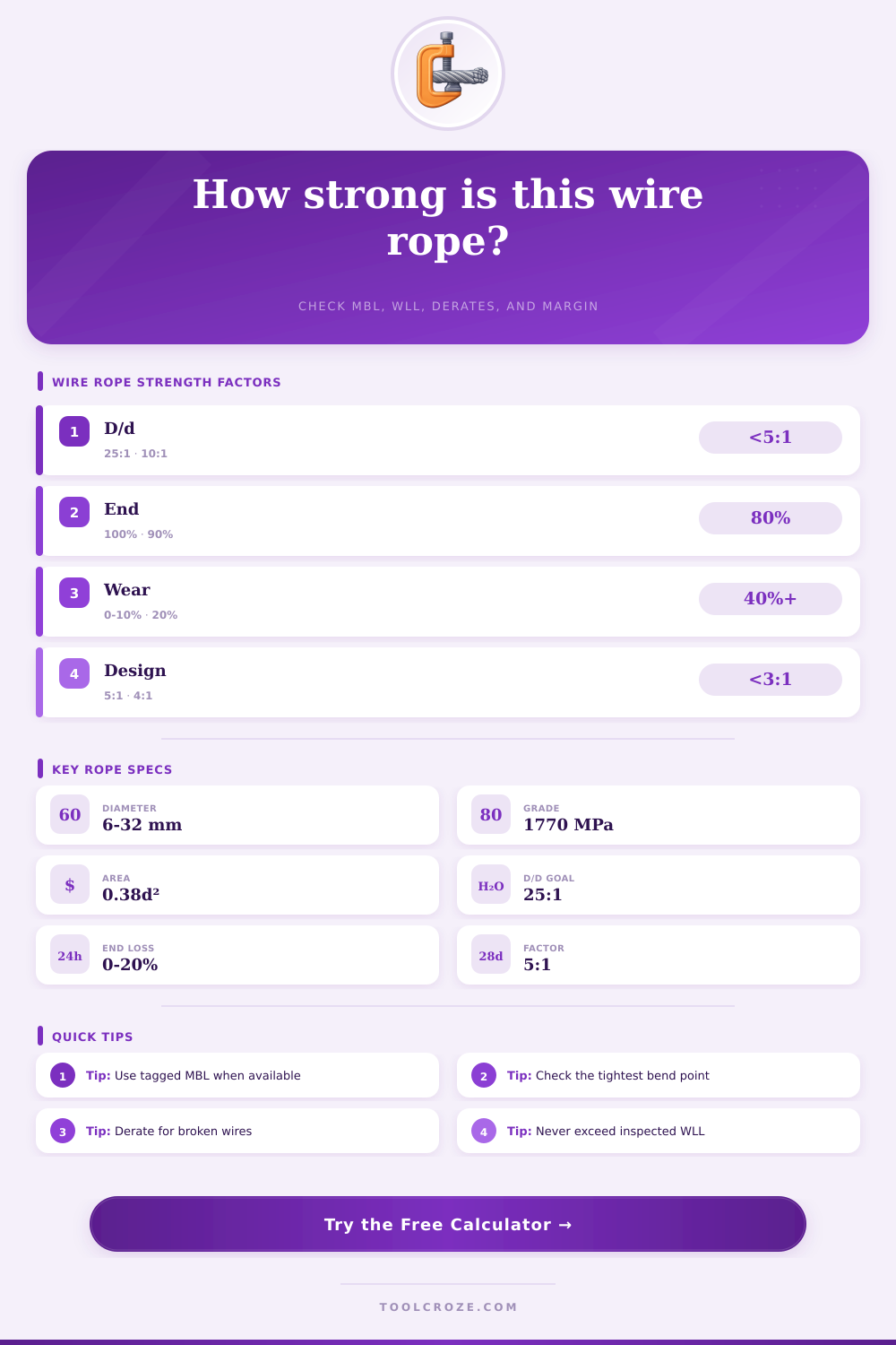
Calculated MBL: MBL(kN) = A(mm²) × grade(MPa) ÷ 1000.
Derated WLL: WLL = MBL × termination efficiency × bend factor × condition factor ÷ design factor.
Utilization: utilization = planned load × dynamic allowance ÷ derated WLL.
📊Rope Strength Spec Grid
📋Construction Metallic Area Factors
| Construction | Typical factor | Strength behavior | Best use in calculator |
|---|---|---|---|
| 6x19 IWRC | 0.380 x d² | Balanced strength and abrasion resistance | Use for general hoisting rope checks |
| 6x36 IWRC | 0.370 x d² | Flexible, slightly lower fill than coarser ropes | Use for slings and flexible running rope |
| 7x19 cable | 0.340 x d² | Many small wires, lower heavy-lift strength | Use for small cable, controls, and light pulls |
| 19x7 rotation-resistant | 0.360 x d² | Good rotation control with handling limits | Use manufacturer MBL when available |
| Compacted strand | 0.430 x d² | Higher metallic fill and higher strength | Use only if the rope is actually compacted |
🔗Termination Efficiency Reference
| Termination | Planning efficiency | What it means | Calculator note |
|---|---|---|---|
| Spelter socket or certified finished rope | 1.00 | Full rated termination basis | Use if tag or certificate confirms it |
| Swaged sleeve or swaged socket | 0.95 | Small loss from forming and fitting | Good planning value for finished slings |
| Hand-tucked eye splice | 0.90 | Efficiency depends on workmanship | Confirm splice standard and inspection |
| Wire rope clips | 0.85 | Highly dependent on clip count and torque | Do not use for overhead lifting unless allowed |
| Wedge socket or temporary end | 0.80 | Lower planning efficiency | Use device instructions before lifting |
➿Bend Ratio Derate Table
| D/d ratio | Bend factor | Rope effect | Planning action |
|---|---|---|---|
| 25:1 or higher | 1.00 | Preferred large bearing surface | Good planning target |
| 20:1 to 24.9:1 | 0.95 | Minor bend efficiency loss | Usually acceptable for screening |
| 10:1 to 19.9:1 | 0.85 | Moderate rope strength reduction | Verify hardware and rope maker limits |
| 5:1 to 9.9:1 | 0.75 | Heavy local bearing loss | Use larger pins, sheaves, or protection |
| Below 5:1 | 0.60 or less | Severe bend and crushing risk | Do not lift without engineered approval |
🔧Design Factor and Condition Guide
| Check item | Typical value | Use when | Stop and inspect when |
|---|---|---|---|
| Design factor 3:1 | Non-hoisting only | Engineered static pull, no people nearby | Any overhead lift is involved |
| Design factor 5:1 | Common lift screen | Preliminary sling strength planning | Critical lift, personnel, or unknown tag |
| Wear derate 10% | Light service loss | Minor surface wear after inspection | Broken wires, kinks, birdcage, heat damage |
| Dynamic allowance 1.25x | Starts and stops | Controlled hoisting with motion | Shock loading or snagged pulls are possible |
💡Wire Rope Calculation Tips
Wire rope does not usually fail in a single moment. Instead, there are several clue that indicate to the rigging engineer when the wire rope will fail. By understanding the various detail about the wire rope and the environment in which the wire rope will be used, the engineer can calculate the strength of the wire rope.
The calculator will run the math for you once you have enter the details of the wire rope and the environment in which it will be used. However, it is essential to understand why each detail modify the strength of the wire rope. The first of the details is the diameter of the wire rope.
Things that affect wire rope strength
This is the starting point for several calculations. The diameter of the wire rope will determine the metallic area that the wire rope will contain. A larger diameter will contain more metal wire.
However, a larger diameter will impact the way the wire rope move over the sheaves and pins. The area factor in the wire rope strength calculator accounts for the fact that the diameter of the wire rope is not comprise entirely of steel. The percentage of metal contained in a 6×19 wire rope with an independent core is not the same than a 7×19 aircraft wire rope of the same diameter.
The area factor can be adjusted so that the calculator accounts for the actual wire rope that you will be using. The grade of the wire rope determine the level of hardness to which the individual wires in the wire rope were drawn. The higher the tensile grade of the wire rope, the more breaking strength the wire rope will have.
However, higher grade will make the wire rope stiffer to move over sheaves. The highest grade of wire rope is typically chosen, but the higher grade will reduce the life of the wire rope and make it more difficultly to handle. This input is placed near the bend ratio because these two factor are often traded off against each other when selecting a grade for a wire rope.
The efficiency of the termination of the wire rope is a factor that causes several error when using the wire rope strength calculator. The wire rope may be in excellent condition along most of its length. However, the termination may limit the strength of the wire rope.
For example, swaged socket will retain most of the strength of the wire rope. However, hand-tucked splice clamp will reduce the strength of the wire rope. This value is applied to the minimum breaking load of the wire rope before the working load limit is calculate.
This prevents the engineer from treating the breaking load of the wire rope as the load that it can be used to lift. The sheaves over which the wire rope run significantly impact the bend ratio of a wire rope. The outer wires of a wire rope will carry more of the load than the inner wire of the wire rope.
A bend ratio of 25:1 will allow the wire rope to retain its full strength. However, a bend ratio of 10:1 or less will remove a significant amount of the strength of the wire rope. The effect of the bend ratio on the wire rope is not linear.
For example, the drop in strength from a bend ratio of 20:1 to a 10:1 will be more significant than the drop in strength from a 30:1 ratio to a 20:1 ratio. Sheaves must be large enough in size to allow for a larger bend ratio in the wire rope. Wire rope will not remain in new condition for long period.
For instance, the wire rope can experience wear on the wire’s surface, snapped wire, and corrosion. These three factor will reduce the amount of load that the metal in the wire rope can take. This input will allow the engineer to select the percentage of the strength of the wire rope that will remain under these conditions.
A 10% derate is used for wire rope that will experience minimal load. However, if the wire rope will be exposed to harsh environment, a higher derate will be used. This number should of be determine from a physical inspection of the wire rope.
The design factor of the wire rope is the number of the wire rope’s load that can be carried before it begin to fail. A 5-to-1 design factor is used in many lifting application. This allows for the additional load that are created when lifting heavy load.
For instance, the design factor allows for the dynamic load of the wire rope and the side load on the wire rope’s hardware. Lower design factor are used for static load of hardware. The results of the wire rope strength calculator will display several number.
The minimum breaking load is the load of the wire rope that is calculate when no variable are accounted for. The derated working load limit is the load of the wire rope after the termination, bend, condition, and design factor have been accounted for. The adjusted load take into account the dynamic load that is selected.
Finally, the utilization rate is the percentage of the derated working load limit that the wire rope will have to carry. If this number reach 85% or above, then the wire rope may be at risk of failing when lifting the load. While this does not mean that the wire rope will fail, if the utilization reaches 85% or above, then each variable in the calculation should be reviewed twice before use.
The conditions under which the wire rope will be used may not be as clean as the specification of the wire rope. For instance, the wire rope may be subjected to temperature that impact the metal within the wire rope. Additionally, dirt and moisture will impact the wear on the wire rope.
The edge of the hardware may be sharper after being subjected to the wire rope for extended period of time. While the engineer may account for these issue when purchasing the wire rope, they are an additional risk for the wire rope. The wire rope strength calculator will not account for these issue.
It is a common practice to calculate the strength of the wire rope with the wire rope that will be used. Another calculation can be performed that uses the next size of wire rope or the next grade of wire rope. The two calculation will allow the engineer to determine whether the wire rope is within its capacity or if it is operating within the limits of the wire rope.
This additional calculation will help the engineer to understand the physical characteristic of the wire rope that will be used. The strength of the wire rope and the demand of the work site require the engineer to understand the physical limit of the wire rope. The wire rope strength calculator will eliminate the need for manual calculation of the strength of the wire rope.
The utilization rate will allow the engineer to understand if the wire rope will be within the physical limit of the wire rope.