Winch Speed Calculator
Compare unloaded speed, loaded speed, cable layer speed-up, voltage drop, load derate, and total recovery time with duty-cycle rest.
Choose a typical winch setup, then adjust the measured motor RPM, gear ratio, drum, cable layer, load, and battery values.
Use no-load motor speed before gear reduction.
Use full-load motor speed, or a realistic loaded estimate.
Example: 156 means motor turns 156 times per drum turn.
Measure the steel drum, not the outside cable layer.
Synthetic rope and steel cable can differ from nominal size.
Outer layers are faster but reduce available pull.
Use the winch rating at the first cable layer.
Estimate rolling resistance, slope, mud, and rigging load.
Reduces available pull for heat, wear, wrap quality, and margin.
Measure while pulling when possible.
The voltage factor scales motor speed.
Adds a practical factor for voltage sag and cable loss.
Distance you need the hook to travel under power.
Recovery time includes calculated cool-down rest.
Loaded Speed
0 ft/min
Voltage and load adjusted
Unloaded Speed
0 ft/min
Same layer, no load
Recovery Time
0 min
Includes duty-cycle rest
Available Pull
0 lb
Layer and derate adjusted
150:1
Common small ATV gear reduction
216:1
Common 4x4 recovery gear reduction
265:1
Common heavy recovery gear reduction
12 V
Automotive winch supply voltage
24 V
Industrial and fleet winch voltage
15-25%
Typical severe-pull duty cycle
| Layer | Speed Effect | Pull Effect | Use Case |
|---|---|---|---|
| Layer 1 | Slowest | Highest pull | Maximum recovery force |
| Layer 2 | Moderate | Slight pull loss | Typical controlled pull |
| Layer 3-4 | Fast | Lower pull | Light or rolling load |
| Layer 5+ | Fastest | Lowest pull | Final hook travel only |
| Voltage Factor | 12 V Reading | 24 V Reading | Expected Speed |
|---|---|---|---|
| Excellent | 12.6-13.8 V | 25.2-27.6 V | Near rated |
| Normal | 11.8-12.5 V | 23.6-25.0 V | Minor reduction |
| Voltage sag | 10.8-11.7 V | 21.6-23.4 V | Noticeably slower |
| Weak supply | Under 10.8 V | Under 21.6 V | Stop and cool/check |
| Rated Pull Class | Typical Motor RPM | Gear Ratio Range | Typical Loaded Speed |
|---|---|---|---|
| 2000-3500 lb ATV | 5200-6500 | 135:1-180:1 | 8-18 ft/min |
| 4000-5500 lb UTV | 5200-6500 | 154:1-198:1 | 7-15 ft/min |
| 8000-12000 lb 4x4 | 4500-6000 | 216:1-265:1 | 4-10 ft/min |
| 15000-18000 lb tow | 3800-5200 | 265:1-315:1 | 3-8 ft/min |
| Duty Cycle | Pull Severity | Run Time Share | Rest Rule |
|---|---|---|---|
| 15% | Severe / near limit | 9 min per hour | Long cool-down |
| 25% | Typical recovery | 15 min per hour | Rest about 3x run |
| 33% | Moderate pull | 20 min per hour | Rest about 2x run |
| 50% | Light load | 30 min per hour | Rest equals run |
A winch that moves slow while a winch is under a load can be frustrating, and a winch that overheats due to the operator misjudging the winch speed and rest cycle can be even more frustrating. The difference between completing one recovery effort versus three recovery efforts with a winch can affect the timing of recovery effort, especially in relation to the setting of daylight. Furthermore, winch speed under load, the voltage input into the motor of the winch, and the number of layer of cable that are wrapped around the winch drum are all interrelated variable; it is beneficial for an operator to have a calculation tool that consider these three factors as well as other winch specifications.
The RPM value of the motor can be used as the starting point of the calculation as each of the other winch specifications is a reduction of the RPM of the motor. The RPM of a winch motor under no load indicates the rate at which the winch drum will rotate if there is nothing attached to the winch hook; the RPM that is provided when the winch is under a load indicates the reduction of that speed that is created when the motor must overcome the resistive forces of the gear train and load of the winch. Additionally, the gear ratio of the winch reduces the RPM of the motor to the winch drum.
Winch Speed and Recovery Time
Higher gear ratio reduce the high RPM of the motor to a slower RPM of the winch drum, allowing the winch to generate more higher pulling forces. The diameter of the winch drum and the number of layers of cable that are attached to the winch drum reduce the pulling force that can be created by each layer of cable. Each layer of cable reduces the effective circumference of the winch drum.
The innermost layer of cable is in contact with the steel winch drum, therefore creating the least amount of pulling force of any layer of cable. Each subsequent layer of cable has a greater radius allowing for greater pulling force at that layer of cable, but with less pulling force available from the winch. Furthermore, the voltage that is provided to the terminals of the winch is rarely the same as the battery voltage that powered the winch; lead voltage loss and warm connections reduce the voltage that reaches the winch motor brushes.
Additionally, the winch condition factor accounts for the voltage loss and state of the battery. Multiplying the motor RPM by the condition factor accounts for the reduction in voltage provided to the motor. Small change in voltage can have a large impact on the RPM of the winch motor when the motor is operating near its maximum torque.
Additionally, load derate is a factor that is often ignored during recovery efforts. The load derate accounts for the fact that the stated load that is published for the winch is under ideal conditions for the winch; the winch is new, the load conditions is ideal, and the load derate is 100%. In reality, the load conditions are often different; the load may be moving through mud, the winch may be on an incline, or the load may have rolling resistance.
By entering a load derate percentage prior to calculating the recovery time, the winch reduces the load that is entered into the winch prior to calculating the winch recovery time. This allows the winch operator to have an honest calculation of the safety factor for the winch operation. Furthermore, the winch recovery time calculator also consider the rest period for the winch in the recovery time that is provided.
The winch calculation accounts for the pulling phase for the winch, but the winch motor must rest for a certain length of time after performing the pulling phase. The duty cycle of the winch can be entered into the winch calculation to automatically add the required rest period for the winch motor after the pulling phase. The total recovery time that is provided to the winch operator indicates the total time that will be experienced during recovery efforts with the winch.
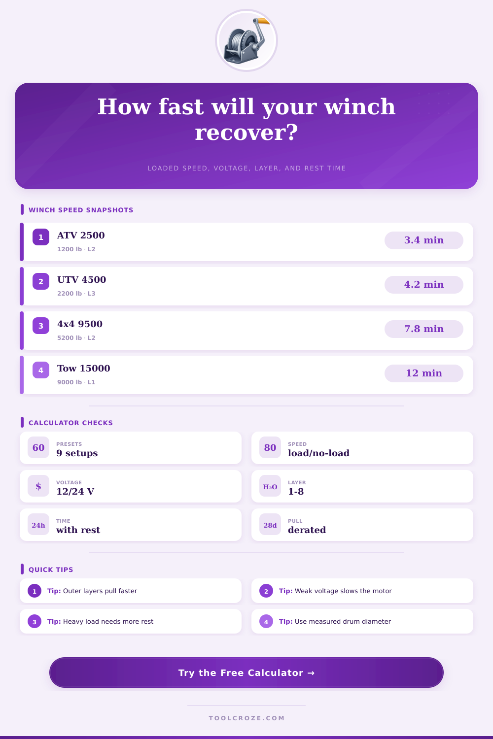
Additionally, there are reference table that provide examples of load capacities for winches of each class and with each level of duty cycle. These tables are not rules, but are examples of the capabilities of winches that can be used. For instance, a 9500-pound winch will perform similarly to a winch with a higher load capacity when the voltage of the winch is reduced and when the load is on an outer layer of cable.
Many people are focused on the maximum line speed that can be achieved by their winch. They are often unaware of the fact, however, that the line speed will be much slower when the winch is under load. The speed that is listed by the winch manufacturer for winchs under no load will be higher than the speed of the line when the winch is under load.
The difference between these two speeds is where many winch operators make mistakes with there winch operation. An understanding of these different load speeds allows for an honest comparison of the winch’s unloaded and loaded speeds. Additionally, the condition of the winch cable can also impact the performance of a winch.
A winch whose steel cable has a kink will have more friction than a winch with a synthetic rope whose strands are flat against the winch drum. These areas of friction will create heat within the winch, which can reduce the speed of the winch’s line as well. Additionally, these areas of friction will reduce the time that a winch operator can perform recovery efforts with that winch.
Therefore, it is important for the winch operator to visually inspect the winch prior to beginning recovery efforts with the winch. Even with favorable winch calculation numbers, the winch operator is required to check the winch’s cable. Finally, the value of the winch calculator is in the ability to test different scenario for recovery efforts with a winch.
The operator can change the cable layer, the voltage, or the load that is being pulled by the winch to assess the impact that each of these factors have upon recovery time. Small changes in voltage or cable layer can have a major impact upon recovery time. The winch calculator allows the winch operator to become aware of these differences, allowing the operator to make better decision about recovery efforts.
For instance, the operator can determine the best point to begin a recovery effort, or if the addition of a snatch block would reduce the distance that the winch motor must travel to move the load of the recovery effort. Finally, while the winch calculator can provide winch operators with a better understanding of the performance that their winch can achieve, the winch calculator is a planning tool only. It is not a substitute for the actual monitoring of the performance of the winch and winch lines during recovery efforts.
A winch that moves slow while a winch is under a load can be frustrating, and a winch that overheats due to the operator misjudging the winch speed and rest cycle can be even more frustrating. The difference between completing one recovery effort versus three recovery efforts with a winch can affect the timing of recovery effort, especially in relation to the setting of daylight. Furthermore, winch speed under load, the voltage input into the motor of the winch, and the number of layer of cable that are wrapped around the winch drum are all interrelated variable; it is beneficial for an operator to have a calculation tool that consider these three factors as well as other winch specifications.
The RPM value of the motor can be used as the starting point of the calculation as each of the other winch specifications is a reduction of the RPM of the motor. The RPM of a winch motor under no load indicates the rate at which the winch drum will rotate if there is nothing attached to the winch hook; the RPM that is provided when the winch is under a load indicates the reduction of that speed that is created when the motor must overcome the resistive forces of the gear train and load of the winch. Additionally, the gear ratio of the winch reduces the RPM of the motor to the winch drum.
Higher gear ratio reduce the high RPM of the motor to a slower RPM of the winch drum, allowing the winch to generate more higher pulling forces. The diameter of the winch drum and the number of layers of cable that are attached to the winch drum reduce the pulling force that can be created by each layer of cable. Each layer of cable reduces the effective circumference of the winch drum.
The innermost layer of cable is in contact with the steel winch drum, therefore creating the least amount of pulling force of any layer of cable. Each subsequent layer of cable has a greater radius allowing for greater pulling force at that layer of cable, but with less pulling force available from the winch. Furthermore, the voltage that is provided to the terminals of the winch is rarely the same as the battery voltage that powered the winch; lead voltage loss and warm connections reduce the voltage that reaches the winch motor brushes.
Additionally, the winch condition factor accounts for the voltage loss and state of the battery. Multiplying the motor RPM by the condition factor accounts for the reduction in voltage provided to the motor. Small change in voltage can have a large impact on the RPM of the winch motor when the motor is operating near its maximum torque.
Additionally, load derate is a factor that is often ignored during recovery efforts. The load derate accounts for the fact that the stated load that is published for the winch is under ideal conditions for the winch; the winch is new, the load conditions is ideal, and the load derate is 100%. In reality, the load conditions are often different; the load may be moving through mud, the winch may be on an incline, or the load may have rolling resistance.
By entering a load derate percentage prior to calculating the recovery time, the winch reduces the load that is entered into the winch prior to calculating the winch recovery time. This allows the winch operator to have an honest calculation of the safety factor for the winch operation. Furthermore, the winch recovery time calculator also consider the rest period for the winch in the recovery time that is provided.
The winch calculation accounts for the pulling phase for the winch, but the winch motor must rest for a certain length of time after performing the pulling phase. The duty cycle of the winch can be entered into the winch calculation to automatically add the required rest period for the winch motor after the pulling phase. The total recovery time that is provided to the winch operator indicates the total time that will be experienced during recovery efforts with the winch.
Additionally, there are reference table that provide examples of load capacities for winches of each class and with each level of duty cycle. These tables are not rules, but are examples of the capabilities of winches that can be used. For instance, a 9500-pound winch will perform similarly to a winch with a higher load capacity when the voltage of the winch is reduced and when the load is on an outer layer of cable.
Many people are focused on the maximum line speed that can be achieved by their winch. They are often unaware of the fact, however, that the line speed will be much slower when the winch is under load. The speed that is listed by the winch manufacturer for winchs under no load will be higher than the speed of the line when the winch is under load.
The difference between these two speeds is where many winch operators make mistakes with there winch operation. An understanding of these different load speeds allows for an honest comparison of the winch’s unloaded and loaded speeds. Additionally, the condition of the winch cable can also impact the performance of a winch.
A winch whose steel cable has a kink will have more friction than a winch with a synthetic rope whose strands are flat against the winch drum. These areas of friction will create heat within the winch, which can reduce the speed of the winch’s line as well. Additionally, these areas of friction will reduce the time that a winch operator can perform recovery efforts with that winch.
Therefore, it is important for the winch operator to visually inspect the winch prior to beginning recovery efforts with the winch. Even with favorable winch calculation numbers, the winch operator is required to check the winch’s cable. Finally, the value of the winch calculator is in the ability to test different scenario for recovery efforts with a winch.
The operator can change the cable layer, the voltage, or the load that is being pulled by the winch to assess the impact that each of these factors have upon recovery time. Small changes in voltage or cable layer can have a major impact upon recovery time. The winch calculator allows the winch operator to become aware of these differences, allowing the operator to make better decision about recovery efforts.
For instance, the operator can determine the best point to begin a recovery effort, or if the addition of a snatch block would reduce the distance that the winch motor must travel to move the load of the recovery effort. Finally, while the winch calculator can provide winch operators with a better understanding of the performance that their winch can achieve, the winch calculator is a planning tool only. It is not a substitute for the actual monitoring of the performance of the winch and winch lines during recovery efforts.
A winch that moves slow while a winch is under a load can be frustrating, and a winch that overheats due to the operator misjudging the winch speed and rest cycle can be even more frustrating. The difference between completing one recovery effort versus three recovery efforts with a winch can affect the timing of recovery effort, especially in relation to the setting of daylight. Furthermore, winch speed under load, the voltage input into the motor of the winch, and the number of layer of cable that are wrapped around the winch drum are all interrelated variable; it is beneficial for an operator to have a calculation tool that consider these three factors as well as other winch specifications.
The RPM value of the motor can be used as the starting point of the calculation as each of the other winch specifications