Welding Speed Calculator
Estimate travel speed from bead size, deposition rate, wire feed speed, joint length, passes, material density, and process efficiency.
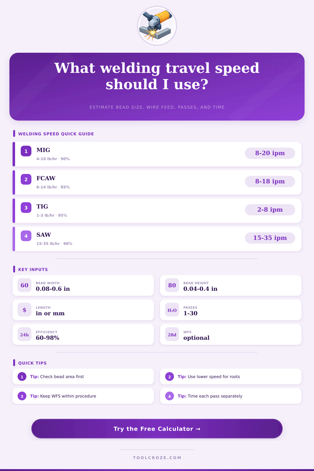
| Process | Typical deposition | Efficiency range | Common travel speed | Typical use |
|---|---|---|---|---|
| GMAW / MIG solid wire | 4-10 lb/hr | 88-95% | 8-20 in/min | Shop fillets, lap welds, plate work |
| FCAW flux-cored wire | 6-14 lb/hr | 78-90% | 8-18 in/min | Structural fillets and field welds |
| SMAW stick electrode | 2-6 lb/hr | 55-75% | 3-10 in/min | Repairs, pipe, and outdoor work |
| GTAW / TIG filler | 0.8-3 lb/hr | 90-98% | 2-8 in/min | Roots, stainless, aluminum, thin sections |
| SAW submerged arc | 15-35 lb/hr | 94-99% | 15-35 in/min | Long seams and heavy plate |
| Profile | Area model | Factor | Use when |
|---|---|---|---|
| Fillet triangle | width x height x factor | 0.50 | Flat or horizontal fillet with equal legs |
| Convex fillet | width x height x factor | 0.65 | Legs include visible reinforcement |
| Groove fill | width x height x factor | 0.85 | V-groove or bevel fill estimate |
| Cap bead | width x height x factor | 0.70 | Surface reinforcement over a filled joint |
| Flat overlay | width x height x factor | 0.90 | Wear-facing or build-up bead |
| Root pass | width x height x factor | 0.55 | Open root or small stringer pass |
| Wire diameter | Mild steel WFS | Approx deposition | Common process |
|---|---|---|---|
| 0.030 in | 180-350 in/min | 2.5-5.0 lb/hr | Short-circuit MIG |
| 0.035 in | 180-420 in/min | 3.5-7.0 lb/hr | MIG sheet and light plate |
| 0.045 in | 180-450 in/min | 5.5-11 lb/hr | Spray MIG and FCAW |
| 0.052 in | 160-360 in/min | 7.0-14 lb/hr | Structural FCAW |
| 1/8 in rod | Hand fed | 2.0-5.0 lb/hr | Stick or TIG rod estimate |
Welding travel speeds is critical to welding processes. Travel speed determine how much heat will go into the weld and what the weld’s shape will be. If the welding torch are traveling too slow, the weld will contain too much heat and the weld bead will be too large.
If the welding torch is traveling too fast, the weld bead will be too thin and there will not be enough penetration into a metal. Because the weld bead’s volume depend on the welding speed, the welder uses the welding speed to calculate how much filler metal will be needed for welding project. The volume of the weld bead depend on the profile of the weld bead.
How Welding Speed Affects Weld Shape and Filler Metal Needed
Weld beads with triangular fillet shapes has a specific volume compared to welds with convex shapes and heavy crowns. The weld with the convex shape and heavy crown have a larger volume of weld bead. For such a weld, more filler metal will be needed and the welder will need to be slower.
Using the wrong weld bead profile will cause issue with the arc time of the weld; the estimated time wont match the actual time for which the weld was performed. Deposition efficiency is another variable that must be accounted for when estimating weld time and effort. For welding processes like MIG welding, some of the filler metal will become spatter.
For welding processes like stick welding, some of the filler metal will become slag and fume. Thus, the deposition efficiency of MIG welding at 90% is much better than stick welding at 60%. Ignoring deposition efficiency will result in underestimating the amount of filler metal need for the weld.
Arc-on factor is another welding variable that must be accounted for. The arc-on factor refer to the amount of time the welding arc is actually on. The time required to complete a welding job include the time to clean the metal pieces being welded together.
An arc-on factor of 65% mean that 35% of the total time is spent performing task other than welding. Thus, the welder must account for the arc-on factor when planning welding jobs to determine the time required to complete the project. The density and conductivity of the metal being welded are another variable.
Metals like aluminum have a different level of thermal conductivity than metals like steel. Aluminum conducts heat away from the weld site more fast than steel does. Therefore, the welder must make adjustments to the travel speed when welding aluminum to maintain proper shaping of the weld’s puddle of molten metal.
If too high a travel speed is calculated for manual welding, such as 30 inches per minute, a human welder will find the weld travel speed too fast to maintain at such a speed. Wire feed speed is another welding variable that can help to confirm if the calculated travel speed for a weld is accurate. For a given wire feed speed, if the welding torch travel slower than the calculated travel speed, the weld bead will be too large.
If the welding torch travel too fast, the weld bead will be too flat. Matching wire feed speed to travel speed will result in a weld of consistent quality. By calculating the deposited weight of the weld, the welder can minimize waste of filler metal and maximize the quality of the weld.
By knowing the deposited weight of the weld, the welder can order the amount of filler metal require for the weld project. This will avoid having excess filler metal inventories. Additionally, by knowing the target travel speed for a weld, the welder can monitor the consistency of the weld.
If the travel speed is off from the target speed, this could mean the voltage is too low or the wire diameters is too large for the joint being welded. These calculations allow the welder to remove the guesswork from establishing welding plans and to know how much time and how much filler metal will be required to complete the weld project.