Welding Inches Per Minute Calculator
Estimate welding travel IPM from bead area, wire feed speed, amperage, wire diameter, deposition rate, material density, and process efficiency.
| Process | Typical amperage | Deposition range | Efficiency | Travel IPM range |
|---|---|---|---|---|
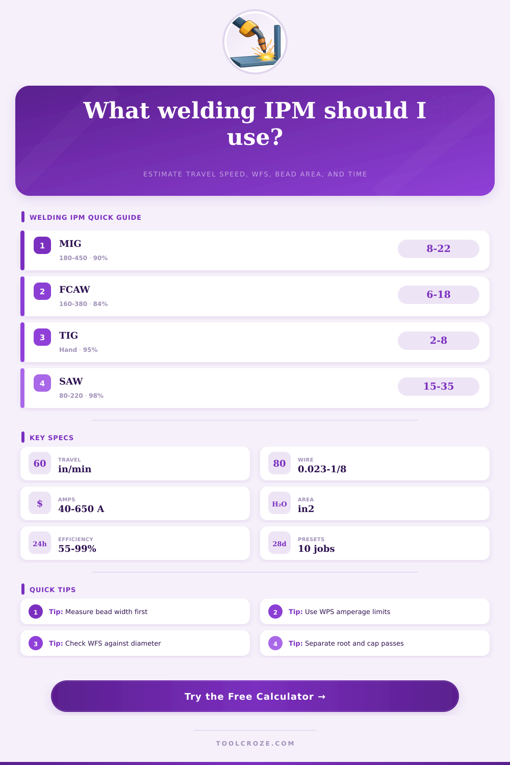
| GMAW short-circuit | 40-200 A | 2-7 lb/hr | 88-94% | 8-22 in/min |
| GMAW spray transfer | 180-420 A | 6-14 lb/hr | 90-96% | 12-28 in/min |
| Gas-shielded FCAW | 160-450 A | 6-16 lb/hr | 78-88% | 6-18 in/min |
| Self-shielded FCAW | 140-360 A | 5-12 lb/hr | 75-84% | 5-16 in/min |
| SMAW stick electrode | 70-280 A | 2-6 lb/hr | 55-72% | 3-10 in/min |
| GTAW / TIG filler | 40-250 A | 0.8-3 lb/hr | 90-98% | 2-8 in/min |
| SAW submerged arc | 350-650 A | 15-35 lb/hr | 94-99% | 15-35 in/min |
| Wire or filler size | Common WFS | Amperage band | Approx gross deposition | Typical use |
|---|---|---|---|---|
| 0.023 in wire | 120-350 in/min | 40-110 A | 1.0-3.2 lb/hr | Thin sheet short-arc |
| 0.030 in wire | 150-420 in/min | 60-160 A | 2.0-5.0 lb/hr | Sheet and light plate |
| 0.035 in wire | 160-500 in/min | 90-220 A | 3.2-8.0 lb/hr | General shop MIG |
| 0.045 in wire | 160-450 in/min | 160-320 A | 5.5-12 lb/hr | Spray MIG or FCAW |
| 0.052 in wire | 140-380 in/min | 220-420 A | 7.0-16 lb/hr | Structural FCAW |
| 1/8 in filler | Hand-fed | 90-180 A | 1.5-4.5 lb/hr | TIG, stick, or SAW checks |
| Profile | Area model | Factor | Best use |
|---|---|---|---|
| Fillet triangle | width x height x factor | 0.50 | Equal leg fillet or tee weld |
| Convex fillet | width x height x factor | 0.65 | Fillet with visible reinforcement |
| Groove fill | width x depth x factor | 0.85 | Bevel, V-groove, or filled joint |
| Cap reinforcement | width x height x factor | 0.70 | Top cap over previous fill passes |
| Flat overlay | width x height x factor | 0.90 | Wear-facing and build-up beads |
| Root stringer | width x height x factor | 0.55 | Pipe root or narrow first pass |
Welding travel speed is one of the critical measurement within the welding field. Welding travel speed directly determines the quality of the weld bead that forms during the welding process. If the welding travel speed is too fast for the metal being welded, there will be issues with fusion between the metals at the weld site.
However, if the welding travel speed is too slow, the weld metal will heat up excess at the site, the weld metal will pile up at the site, and the weld site may crack. Welding travel speed is measured in inch per minute. In order to weld a metal successfully, welders must calculate the proper inches per minute that the weld should travel at to pass an inspection.
How to Calculate Welding Travel Speed
In order to calculate proper welding travel speed, a welder must understand several specific value. A welder needs to know the area of the weld bead that they are attempting to fill. Additionally, the welder must know the deposition rate of the metal being welded, the process efficiency, and the density of the weld metal.
The deposition rate of metal is not the same as the amount of filler metal that will remain in the weld. Some metal will be lost to spatter, slag, and stub loss. The process efficiency value determine the percentage of filler metal that will remain after metal loss.
Additionally, welders also must know the density of the metal being welded. When these four values are combined, the welder can determine the proper welding travel speed to use when welding. The shape of the weld bead can impact the welding travel speed.
Welding travel speed is dependent upon the area of the weld that must be filled. For fillet welds with equal leg, the cross-section of the weld will be a triangle. For fillet welds with reinforcement, the weld will have a convex shape.
The increased area of the weld creates an impact upon the required welding travel speed. Different type of joints will impact the area of the weld that is created. For instance, root passes for pipes will be narrow and thin, while the hardfacing layer of weld metal will be wide and shallow.
The change in the weld profile will alter the area of the weld, which will impact the welding travel speed that is required for that weld. Process efficiency is one of the critical factor in calculating welding travel speed. For short-circuit MIG welding, the process efficiency is approximately 90%.
This means that 90% of the metal stay in the weld. For stick electrode welding, the process efficiency is approximately 60%. This is due to the additional metal loss caused by stick welding.
Self-shielded flux-cored wire is somewhere in between short-circuit MIG welding and stick welding process efficiency value. The value of process efficiency is important in that if it is not include in the equation, the travel speed will be calculated incorrectly. Wire diameter and wire feed speed are two additional factor that will impact the deposition rate.
If the welder increases the wire diameter, the deposition rate will also increase. Similarly, if the welder decreases the wire diameter, the deposition rate will also decrease. However, if a smaller diameter wire is used at a higher feed speed, it will have the same deposition rate than a larger diameter wire traveling at a lower feed speed.
Welding calculators allow welders to program different wire diameters and wire feed speeds to determine the deposition rate that is created. A significant difference between the calculated deposition rate and the feed speed will require welders to investigate their wire size, metal density, and process efficiency. Additionally, amperage and voltage also impact welding travel speed.
For short-circuit welding, the amperage should be 200 amp or less to maintain a stable welding arc. For spray welding processes, amperage will need to be more higher. Additionally, voltage will need to be higher for spray welding processes.
If welders use an amperage that is outside the parameters for the welding process that they are using, the welding travel will create an unstable welding arc. The density of the metal impacts welding travel speed. Aluminum metal has a low density, meaning that the aluminum weld bead will weigh less than a carbon steel weld bead of the same size.
Because of this, the welding speed can be faster for aluminum metal than steel metal. Additionally, other metals like nickel alloy and copper have higher metal densities. These metals will require different welding speeds than metals like aluminum and steel.
The arc-on factor is a measurement that welders often ignore. However, it is important in the scheduling of welding jobs. The arc-on factor accounts for how much time is spent welding versus how much time the welding job will take on the clock.
If a welder has an arc-on factor of 65%, it means that for every minute of welding, 90 seconds of clock time will pass. Both pure arc time and arc-on time must be accounted for in scheduling welding jobs so that the number of welding passes within a shift can be calculated. Common error in welding travel speed calculations include only measuring the width of the weld bead instead of the height of the weld.
Another common error is using the deposition rate of the metal without accounting for the process efficiency. Additionally, another error is treating root passes, fill passes, and cap passes as if they are the same size as each other. Each pass has a different target area for the weld metal, so each pass will have a different welding travel speed.
Heat input is another factor in welding. The heat input must be within certain limit for the weld. Welding travel speed will impact the heat input even with the same amperage.
Calculating the heat input in kilojoules per inch will allow welders to ensure that the welding travel speed for certain metals is within the limits for that metal. Finally, welders should always run a test pass for weld travel speed calculations. Using a weld test pass, welders can measure the width and the height of the weld bead.
These measurements can then be compared with the calculations. If the calculations match the measurements of the weld pass, then the welding parameters for the metal are set to the correct values. If the measurements do not match the calculations, welders must investigate their welding technique, their shielding gas, and the condition of their metal being welded.