Gas pressure is another important component of the welding process. The gas pressure must be managed correctly to ensure that the quality of the weld are satisfactory. If the gas pressure is incorrect, there could be hole in the weld, or the welding torch could spit metal out of the weld.
Many welding problems is caused by incorrect amount of shielding gas that reach the weld, so the gas must reach the weld at the correct rate. The chart provides information regarding the regulator settings for different metal types and thicknesses. Shielding gas is critical in welding because it protects the weld from coming into contact with air.
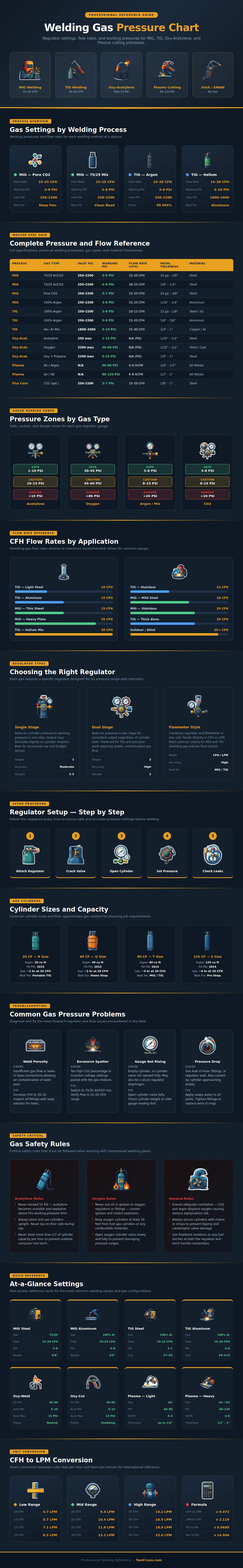
Gas Pressure in Welding
Shielding gas keep oxygen and nitrogen out of the weld. Using too little shielding gas will cause porosity in the weld. Using too much shielding gas will cause turbulence in the weld.
Turbulence will cause air to be pulled into the weld. Therefore, there is a specific range of gas pressure that should be maintained during welding. There is also a difference between the inlet pressure and the working pressure of the welding gas.
The pressure of the gas cylinder can read as high as 2,000 PSI. However, the regulator will lower that pressure to a lower PSI before the welding torch recieve the shielding gas. Any difference between these two types of pressure will tell you whether the regulator for the welding torch is working correct or whether there is a leak or blockage in the system.
The welding process will require a different gas pressure. The role of the gas will change according to the welding process that is being used. For instance, MIG welding will require more CO2 to assist in the penetration of the thick steel.
TIG welding will require a gentler gas flow because of how the welding torch work. Argon gas will behave differently than a helium gas mix. Plasma cutting will require a different scale of gas pressure than MIG or TIG welding.
Each of these different gases will conduct heat at a different rate. Thus, they will require different volumes of the gas to flow at the weld to allow the metal to be cut at the weld at the typical rate of the welding torch. The type of regulator that the welder will use for the welding torch will affect the gas pressure of the shielding gas while welding.
A single stage regulator is a simple device and costs less money than a dual-stage regulator. However, as the gas within the cylinder is used up, the outlet pressure of a single-stage regulator will change. A dual-stage regulator will hold the pressure of the shielding gas for a longer period of time.
This will be very helpful for welding processes like aluminum or stainless steel welding because these metals will exhibit small changes in gas flow. Another type of regulator features a flowmeter-style regulator. This type of regulator will read the amount of gas that is flowing in cubic feet per hour so that the welder does not have to use mental math in determining the amount of shielding gas in the mixture.
The size of the gas cylinder will also impact how often gas pressure will change in the welding torch. Small gas cylinders are helpful for short welding jobs. However, the pressure of the gas will drop faster in a small welding cylinder when welding continuous.
Gas cylinders that are large in size will cost more money to refill with shielding gas. Additionally, they will be more difficult to move from one place to another in the shop. However, the large gas cylinder will keep the welding torch pressure more stable so that it does not run out of shielding gas during the welding process.
There will be symptoms of a bad weld that can be used to identify the specific cause of the defective weld. Porosity in the weld indicates that the shielding gas are not reaching the weld. The shielding gas could not reach the weld due to a loose fitting of the torch or due to the wind blowing the shielding gas away from the weld.
Another symptom of a bad weld is that the MIG welding torch will spit metal. This indicates that the mix of shielding gas is incorrect or that the shielding gas flow is too low. If the gauges on the welding torch do not move when the welding process is started, this indicates the welding cylinder is empty or the valve is not open.
These symptoms will help the welder to identify the cause of the bad weld using the information provided in the troubleshooting section of the chart. There are specific safety rules that must be followed when using shielding gases. Acetylene gas, for instance, will become unstable if the pressure of the acetylene goes above fifteen PSI.
Oxygen and oil will ignite if they come into contact with each other. Thus, you must keep oxygen away from oil-based metals. The gas cylinder must always be chained and upright so as to not become mobile in the case of a broken valve on the cylinder.
Welders must become familiar with using the gas pressure and flow settings to monitor the welding process. If the weld bead looks good but too much shielding gas is used, there is a problem with the welding technique. If there are the correct settings for gas pressure but the weld fails, there is a problem with the flow of the shielding gas to the welding torch.
Thus, the welder should never solely rely on the settings on the regulator for the welding torch. However, the welder should monitor and check the flow of the shielding gas at the welding torch so that the welder ensures that the weld will be correct.
