Welding Consumable Calculator
Estimate deposited weld metal, filler metal to issue, electrode or wire length, shielding gas volume, flux or slag allowance, pass count, stub loss, and waste factor.
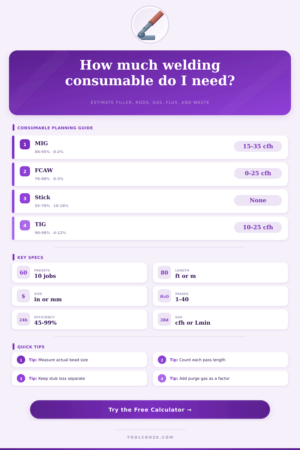
These cards update from the selected process, material, and joint profile.
| Process | Typical deposition efficiency | Typical stub or remnant | Gas or flux factor | Consumable note |
|---|---|---|---|---|
| GMAW / MIG solid wire | 88% to 95% | 0% to 2% | 15 to 35 cfh gas | Low stub loss; spatter and starts drive waste. |
| Gas-shielded FCAW | 78% to 88% | 0% to 3% | 20 to 45 cfh gas | Slag and wire type reduce net deposited yield. |
| Self-shielded FCAW | 75% to 85% | 0% to 4% | No shielding gas | Use slag factor for cleanup and wire yield planning. |
| SMAW stick electrode | 55% to 70% | 10% to 18% | No shielding gas | Stub length and slag coating are major allowances. |
| GTAW / TIG filler rod | 90% to 98% | 4% to 12% | 10 to 25 cfh gas | Rod remnants and purge time often matter most. |
| SAW submerged arc | 94% to 99% | 0% to 2% | 0.6 to 1.2 flux | Flux recovery rate changes the issued flux amount. |
| Reference item | Planning value | Use for | Calculation note |
|---|---|---|---|
| Fillet triangle | 0.50 area factor | Equal leg fillets | Area = leg x throat or leg x leg x 0.50. |
| Convex fillet | 0.65 area factor | Reinforced fillets | Use when measured bead includes visible convexity. |
| Groove fill | 0.85 area factor | V-groove estimate | Average width and depth should represent each pass. |
| 0.035 in wire | 0.00096 in2 | MIG sheet and light plate | Wire length rises quickly when diameter is small. |
| 0.045 in wire | 0.00159 in2 | MIG spray and FCAW | Common shop planning diameter for heavier beads. |
| 1/8 in rod | 0.0123 in2 | Stick and TIG checks | Rod count depends strongly on usable rod length. |
| Consumable | Typical range | Factor input | When to increase |
|---|---|---|---|
| MIG shielding gas | 15 to 35 cfh | Gas flow and 5% to 20% | Long hose purge, frequent starts, draft, or large nozzle. |
| TIG argon | 10 to 25 cfh | Gas flow and 10% to 60% | Purge dams, trailing shields, preflow, and postflow. |
| FCAW shielding gas | 20 to 45 cfh | Gas flow and 5% to 25% | Outdoor screens, higher nozzle standoff, or high current. |
| SAW granular flux | 0.6 to 1.2 per lb | Flux factor | Low recovery rate, damp flux discard, or short seams. |
| Stick electrode coating | 0.10 to 0.25 per lb | Flux factor | Heavy coating classes or high slag removal allowance. |
When you are planning a heavy frame project, you have to determine how many spools of wire and how many cylinder of gas you need to complete the project. You should not guess the amount of wire and gas you will need for the project. If you order too little, your welding crew will sit idle while they await teh arrival of a delivery truck with the ordered materials.
However, if you order too much wire and gas, you will have thousands of dollars of filler metal to deal with while it sits on a shelf collecting dust for three years. The amount of metal that you buy is not the same as the amount of metal that ends up in your weld joint. This is precisely why you need to calculate how much filler metal you will need for your project.
How to work out how much welding wire and gas you need
The difference between the amount of metal that you purchase and the amount that ends up in the weld joint is call deposition efficiency. Deposition efficiency will vary based on the welding process that you use to deposit the metal into your weld joint. If you use MIG welding, for instance, there will be minimal waste of the filler metal because a MIG welding setup push the wire into the hole.
However, if you use stick welding, there will be waste in the form of slag and flux that does not become part of the weld joint. Stick welding also features the loss of the welding electrode stubs. You must discard the welding electrode and toss it into a scrap bin for weld metal before the weld is complete.
If you use hundreds of stick welding electrode daily, those lost stubs will add up to a significant portion of your welding metal spending. Another factor to consider when calculating the amount of filler metal that you will need for your project is the geometry of the weld bead. The weld bead is a volume of metal, not a line.
Many people calculate the length of the weld bead but fail to calculate the volume of the weld. The volume of the weld will change if the weld joint feature a triangle weld or a convex weld bead. A convex fillet weld will use up more metal than a flat fillet weld with the same leg size.
You must take this convexity of the weld joint into account when calculating the amount of metal needed for the weld project. Otherwise, you will find yourself with an underestimation of the amount of metal needed for your project, and you will break your budgets. Shielding gas is another cost that you must consider when calculating your metal requirements.
The shielding gas will flow when you pull the trigger to start the welding process. The shielding gas will continue to flow after you stop welding and the welding process is complete. On projects that have many stitch weld, this will waste alot of shielding gas.
Welding shops use the gas factor to account for the waste of shielding gas when they perform this type of calculation. The gas factor accounts for the shielding gas that will flow during the purge of the joint before welding and while welding is in progress. In the shop environment, the shielding gas factor may seem like a small detail that can be left out of your calculations.
However, if the welding project is taking place in a drafty area of the shop or if the shielding gas is delivered through a long hose from the shielding gas tank, this factor will have a significant impact on the total amount of shielding gas that will be consume during the project. Material density is the next factor that you must consider when performing your calculations. The weight of the metal will change based on the material that is used.
If you use carbon steel for your project, which is the most common metal used in welding projects, the density of the metal is 7.85 g/cc. However, if you use aluminum or nickel alloys for your project, the density of those metals are different. Aluminum metal, for instance, weighs significant less than carbon steel.
If you use the density of carbon steel to calculate the weight of the metal you will use for your aluminum project, you will have incorrect calculations. Welding shops use a tool that allows you to swap the material families in your calculations. By using this tool, the tool will automatically account for the density of the metal in your calculations, and you will have accurate estimates of the metal that will be used in your project.
If you are performing welding work on a metal joint that requires more than one pass to complete, the complexity of the calculations increases. The root pass of the weld joint produce a thin stringer of weld metal. However, the fill passes and the cap pass will be much wider.
You should not use an average calculation for each pass of the weld joint. By using an average value, you introduce errors into your calculations. You should calculate the root pass of the weld joint separately from the fill passes and the cap pass.
By calculating each pass separately, you can accurately calculate the total amount of metal that will be used in your project. Although it is more work to calculate each pass of the weld joint separately, by doing so you will not run out of metal during the final pass of your weld joint project. Although the estimates that you calculate for the amount of metal that will be used in your project are a great starting point for the metal purchase for your project, you should also include a planning waste factor into your calculations.
Welders will leave a larger bead on the metal project than the specification that are listed in the blueprint for the project. This is due to welders being too heavy on the welding trigger. To account for this waste of metal, you should add a ten or fifteen percent buffer to the estimate that you make for the metal that will be used.
This buffer will act as a safety net in case metal gets wasted in the project and your welding shop isnt experiencing a production shutdown due to a lack of metal for the weld joint. The precision with which you plan your welding metal project will determine the precision with which you price your project. This goes from guessing the amount of metal needed to engineering your weld joint project.
You can show your clients that you understand the physics of the weld joint project by providing them with a detailed explanation of the amount of metal that you need for there welding job. If you account for slag, welding stubs, and shielding gas purges, your welding shop will remain profitable, your projects will be completed on time, and you will not find yourself in a situation where you run out of wire when the project is almost finished.