Weld Weight Calculator
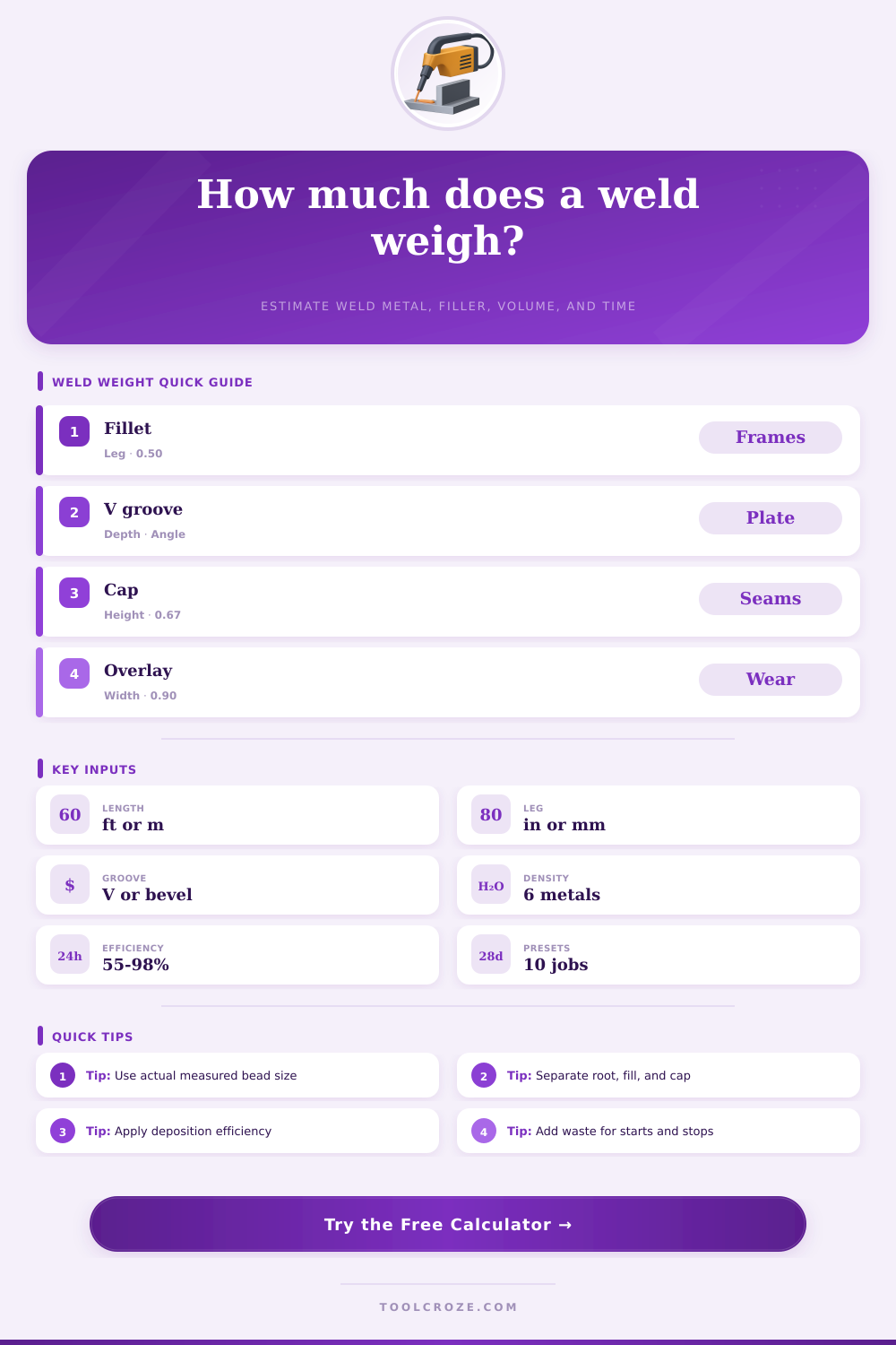
Estimate deposited weld metal, filler issue weight, weld volume, equivalent throat, mass per length, and arc time for fillets, grooves, caps, and overlay beads.
| Geometry | Area model | Best input | Takeoff note |
|---|---|---|---|
| Equal-leg fillet | 0.5 x leg x leg x profile | Measured leg size | Use final weld size, not every pass, unless estimating pass-by-pass filler. |
| Unequal fillet | 0.5 x leg A x leg B x profile | Both leg dimensions | Useful for skewed clips, lap joints, and intentionally unequal welds. |
| V-groove or bevel | Average width x fill depth | Root gap, depth, angle | Add cap reinforcement separately if the drawing specifies crown height. |
| Overlay or cap | Width x height x shape factor | Bead width and height | Use 0.67 for rounded cap and about 0.90 for flatter overlay passes. |
| Weld metal family | Density lb/in³ | Density g/cm³ | Common planning use |
|---|---|---|---|
| Carbon steel | 0.283 | 7.83 | Structural frames, plate, pipe, brackets, and general fabrication. |
| Stainless steel | 0.289 | 8.00 | Food equipment, tanks, sanitary piping, and corrosion resistant assemblies. |
| Aluminum alloy | 0.098 | 2.70 | Rails, frames, covers, marine parts, and lightweight structures. |
| Nickel alloy | 0.296 | 8.19 | High temperature, chemical service, and corrosion resistant welds. |
| Silicon bronze | 0.319 | 8.83 | Braze welding, sheet repairs, and dissimilar metal deposits. |
| Hardfacing alloy | 0.285 | 7.89 | Wear strips, buckets, crusher parts, rollers, and rebuild layers. |
| Process | Typical efficiency | Planning speed | Weight note |
|---|---|---|---|
| GMAW / MIG solid wire | 88% to 95% | 8 to 20 in/min | High transfer efficiency; issue weight is close to deposited weight. |
| FCAW flux-cored wire | 78% to 88% | 6 to 14 in/min | Include slag, spatter, and wire trim allowance for field work. |
| SMAW stick electrode | 55% to 70% | 3 to 8 in/min | Stub loss and slag make issued electrode weight much higher. |
| GTAW / TIG filler rod | 90% to 98% | 2 to 8 in/min | Good for small welds; filler use depends heavily on operator technique. |
| SAW submerged arc | 95% to 98% | 18 to 40 in/min | Use separate flux recovery or loss factors outside this weld metal estimate. |
Weld weight is an important factor for the fabricator in that weld weight impact the orders for the filler metal that is to be used in the welding processes, as well as the labor estimates that will be used for that same welding job. If the person who calculates the weld weight for a particular job calculates the weld weight incorrectly, then the person may either experience a shortage of the filler metal required to complete the welding job, or the filler metal may be left on the floor due to the extra metal that will be wasted. In order to obtain an accurate estimate of the amount of filler metal that will be required for a welding job, it is first important to understand the various ways in which weld weight can be measured.
Weld weight isnt the same as the size of the weld bead that will be completed. The welder must calculate the weight of the metal that is deposited into the joint, as well as adjusting for the density of the metal that will be used. Many welds that is made have different characteristics than the welds depicted on the engineering drawings for those jobs.
How to Calculate Weld Weight and the Metal You Need
For instance, a fillet weld may appear as a triangle on a drawing, but the actual weld may not be even with each of the members that are being welded; such differences will contribute to the additional metal that must be deposited into the weld. Similarly, the amount of filler metal required for a single-pass tack weld will be different than the metal required for a weld that has multiple passes. To calculate the weld weight for a job, the welder must use various input factors.
For fillet welds, the welder must use the leg length of the weld. For plate joints, the welder must use the depth of the groove and the included angle of the joint. For cap welds, the welder must use the height of the reinforcement of the weld.
The area of the weld can be found by multiplying the area of the cross-section of the weld by the length of the weld. The density of the metal can be used to find the weight of the metal that will be deposited into the joint. The density of the metal is an important factor in that the density of aluminum metal is different than the density of carbon steel.
Thus, if the metal is changed from carbon steel to aluminum metal, the weld weight will be different. Finally, the efficiency and the amount of metal waste from the welding process must be accounted for in order to calculate the total amount of filler metal that will be required for the welding job. Processes that have low welding efficiencies will have more metal waste than processes with higher efficiencies, meaning that more metal will have to be ordered for a process with low welding efficiency than for a process with high welding efficiency.
Common errors in calculating the weld weight include only using the drawing of the metal joint to determine the size of the weld. For instance, the drawing for a joint may show that the size of the fillet weld should be 3/8 inch in thickness, but the welder may create welds that are 7/16 inch in thickness. Because 7/16 inch is greater than 3/8 inch, using the dimensions from the drawing will result in an underestimation of the weight of metal that will be used in creating those welds.
An underestimation of the metal will result in a shortage of metal for the weld. Similarly, if the measurements for the root gap or reinforcement height are ignored for groove welds, the metal will again be underestimated for those welds. Another factor to consider is the number of welding passes that will be used to create the weld.
If the weld is to be created in multiple passes, it is possible to model each pass as having the same cross-sectional area as the entire weld; in such cases, the welder may need to calculate the weld in relation to each pass separately. For instance, if the welding job includes a five-pass groove weld that is to be completed in a single pass, the amount of metal that is used will be less than if each pass is accounted for separately. The welding process will impact both the efficiency with which the weld is created, as well as the amount of metal that must be ordered.
For instance, a shop may use solid wire metal for welding projects, and solid wire metal has high welding efficiency. However, stick electrodes may be used in the field for welding projects, and stick electrodes have low welding efficiencies. Thus, if there is a change in welding process without a change in efficiency, there will be either a shortage of filler metal for the weld, or there will be a surplus of filler metal that cannot be used.
Another factor to consider in the estimation of the time that will be spent welding is the travel speed of the welding machine and the operating factor of the welding machine. The estimate for the welding time will include both the travel speed and the operating factor. Time includes not just the welding time, but also the time required for setup of the welding machine, movement of the machine in relation to the metal joints to be welded, and inspection of the welds for quality.
These reference tables is useful in that each table includes variables related to welding processes. For instance, the tables include models of the geometry of the welds, density values of various metals, and the efficiencies of welding processes. Many welding jobs include complications that are beyond the abilities of the calculator to account for.
For instance, if the welds are short or if the welds are scattered across the metal being welded, more allowances will be required for starting and stopping the welding process. Similarly, if any portion of the weld is to be repaired, more metal will be required for the repair of that weld. Additionally, field conditions, such as wind or temperature, will contribute to additional spatter of metal from the welding process, as well as may impact the travel speed of the welding machine.
These complications will have an impact upon the amount of metal that is consumed during the welding process and the length of time that it takes to complete that weld. In calculating the amount of metal that will be required for the weld, it is first possible to calculate the amount of metal that will be required under shop conditions, and then to add a contingency for any potential complications for the welding job. Overall, the goal for calculating the weld weight for a job is to create a repeatable method for determining the amount of metal that is required, as well as the labor for completing that weld.
If the amount that is calculated for the metal and labor is similar to the actual amount of metal that is consumed and actual labor for completing the weld, the fabricator will avoid either shortages of metal for the weld or the need to have too much metal that is unused and sitting on the floor as spools of metal. You should of considered that alot of metal might be wasted.