Weld Shear Strength Calculator
Estimate weld throat area, allowable shear strength, eccentric load effect, and demand utilization from weld type, length, electrode strength, and safety factor.
📌Units and named weld presets
Presets are screening examples. Enter the actual effective weld length, electrode classification, and qualified procedure values for production work.
🔧Weld shear inputs
Weld shear strength result
📊Core shear factors
📋Weld shear reference tables
| Weld type | Effective throat model | Typical use | Screening note |
|---|---|---|---|
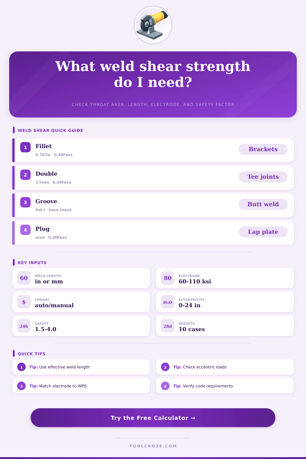
| Single fillet | 0.707 times leg size | Lap joints, brackets, tabs | Use effective length excluding crater starts when required by the job specification. |
| Double fillet | 0.707 times leg size times two lines | Tee joints, centered shear lugs | Balanced welds reduce secondary bending when load passes near the weld group center. |
| Complete groove | Connected thickness or qualified throat | Butt joints and splice plates | Check base metal, fusion, backing, and procedure requirements in addition to shear. |
| Partial groove | Prepared groove depth times factor | Built-up members | Use the qualified effective throat from the WPS when it differs from geometry. |
| Plug or slot | Effective shear area by weld throat | Lap plates and sheet attachments | Spacing, hole size, and base metal tearing often govern before weld metal shear. |
| Electrode class | Nominal strength | 0.30Fexx shear | Common application |
|---|---|---|---|
| E60XX | 60 ksi or 414 MPa | 18 ksi or 124 MPa | Light structural and general carbon steel repair work. |
| E70XX | 70 ksi or 483 MPa | 21 ksi or 145 MPa | Common structural fillet weld electrode family. |
| E80XX | 80 ksi or 552 MPa | 24 ksi or 166 MPa | Higher strength low-alloy weldments where specified. |
| E90XX | 90 ksi or 621 MPa | 27 ksi or 186 MPa | Matched filler for selected high strength steels. |
| E110XX | 110 ksi or 758 MPa | 33 ksi or 227 MPa | Only when the base metal and procedure call for it. |
| Eccentricity | Calculator factor | What it means | Better practice |
|---|---|---|---|
| 0 to 10 percent of weld length | Minor reduction | Load is near the weld group centerline. | Keep the reaction path close to the weld group centroid. |
| 10 to 25 percent of weld length | Moderate reduction | Secondary moment may add shear at the weld ends. | Lengthen the weld group or add a return weld where permitted. |
| 25 to 50 percent of weld length | Large reduction | End loading and rotation become important. | Use a weld group analysis instead of a single-line screen. |
| Above 50 percent of weld length | Severe reduction | The simplified capacity screen is highly sensitive. | Redesign the connection geometry or request engineering review. |
| Check item | Why it matters | Input to adjust | Shop action |
|---|---|---|---|
| Effective length | Shorter welds give less throat area. | Weld length and line count | Measure only the length that can carry the shear path. |
| Fit-up quality | Gaps, access, and stops reduce practical capacity. | Quality factor | Use the lower factor when access or inspection is limited. |
| Electrode match | Strength must match the approved filler and base metal. | Electrode strength | Confirm the WPS, filler classification, and consumable storage. |
| Load path | Eccentricity adds moment and raises end stress. | Eccentricity and direction | Move the line of action closer to the weld group if possible. |
| Governing limit | Base metal tearout or block shear may control. | Not modeled here | Run the code checks for connected parts before approval. |
Welded connection are the parts of the structure that experience the highest level of stress. Welded connections, however, often are not visually inspected once the structure are painted. The welded connection may look good on the outside, but it could fail in shear within the throat of the weld if the throat size is not properly judged or if the strength of the welding electrode is underjudge.
A shear capacity calculator can help engineers and fabricators to determine the shear capacity of the welded connection prior to cutting the steel for that structure or prior to schedule an inspection. To calculate the shear capacity, the engineer enters the weld type, size, length, and the electrode classification into the calculator. Additionally, the amount of eccentricity of the load and the safety factor for the weld must also be entered into the calculator.
How to Check Weld Shear Strength
While this calculator does not replace code checks and procedures performed by a qualified fabricator, the number provided by the calculator will tell a designer or fabricator whether a weld is comfortable or tight. All of the variables that must be entered into the calculator are the same variables that would be found on the drawings of the structure. One of the most important variables that is often underjudged in the design of welded connections is the effective throat.
For fillet welds, the effective throat is 70% of the leg size of the weld. For groove welds or double fillet welds, the effective throat is calculate differently. When the user changes the weld type in the calculator, the effective throat automatically recalculates within the software.
The effective throat size will impact the allowable load of the welded connection. If a quarter-inch fillet weld 8 inch in length will allow for a certain amount of load, a quarter-inch fillet weld used as a double fillet on both sides of a tee joint will allow almost twice the load through the weld. Another variable that impact the shear strength of a welded connection is the strength of the welding electrode.
For instance, the shear stress produced by an E70 welding electrode will be higher than an E60 welding electrode. Because of this, when the E70 and E60 welding electrodes are within close proximity to one another in a welded connection, the strength of the E70 will be critical in determining if the weld passes or fail. The classification of the welding electrode must, therefore, be entered into the calculation.
In addition to the electrode strength, the quality factor for the weld and the direction factor can also be entered into the calculator. For instance, a shop weld that is loaded in a transverse direction will have more strength than a field weld loaded in a peel direction. These variables allow the results from the software to be realistic to the shop and the weld conditions.
The factor of eccentricity of the load placed upon the welded connection is one of the more difficult to account for with the engineer’s intuitions about the strength of the weld. Any load that is eccentric to the centroid of the welded group will place a moment upon the weld, which will increase the shear stress upon the ends of the weld. The software accounts for the eccentricity of the load by applying a reduction factor to the allowable load of the weld.
The more eccentricity of the load entered into the program, the lower the allowable load upon the weld. The allowable load of the welded connection will be reduced if the ratio of the applied load to the allowable load is greater than 1.0 after the eccentricity is account for. In this case, the weld should be lengthened or the point of attachment to the member should be moved.
Another variable that is entered into the calculator is the safety factor. The designer or fabricator enters the safety factor as an explicit input. For most screened welded connections, a safety factor of 2.0 is used.
For other connection like lifting lugs, higher safety factor are used. This safety factor is applied after the allowable shear stress is calculated for the weld and the eccentricity of the load is account for. By viewing the safety factor input, the designer can see how many units of strength are lost when the safety factor changes from 2.0 to 3.0.
Tables are provided beneath the input lines for the software. One table describes the effective throat models for various types of welds. A second table lists the 0.30 Fexx value for various types of welding electrodes.
A third table lists the various meanings of eccentricity value. These tables are not a replacement for the engineers judgment of a welded connection, but they do give additional context for the engineer when the calculated allowable load is near the allowable load. As with all projects, there will be variables in the actual welded connection that differ from the calculations.
For instance, the fit-up of the welds may not allow for the theoretical weld size. The access to the weld may not allow for the theoretical length of the weld. These types of variable are accounted for through the quality factor for the weld.
However, other variable must also be accounted for by the designer. For instance, base metal tear-out, block shear, and fatigue are not accounted for in the weld shear capacity calculator. Regardless of the size and strength of the weld calculated through this software, checks for base metal tear-out, block shear, and fatigue must still be performed once the weld has passed the shear stress calculation for the weld.
By running the calculator twice, time can be save in the fabrication shop. The weld variables can be entered into the calculator the first time using the nominal value. The second time, the quality factor can be lowered or the eccentricity of the load can be increase to reflect the conditions that will exist in the shop when the weld is fabricated.
If both calculations remain within the allowable load for the welded connection, the weld is likely fine. If the second calculation approaches the allowable limit for the weld while the first does not, there is an issue with the assumption used to fabricate the welded connection. Weld shear strength is a question of area, stress, and load path.
The shear capacity calculator makes all of these variable visible to the designer and fabricator at the same time.