Weld Neck Flange Weight Calculator
Estimate weld neck flange weight from nominal pipe size, flange outside diameter, tapered hub dimensions, flange thickness, bore, raised face, bolt holes, quantity, and material density.
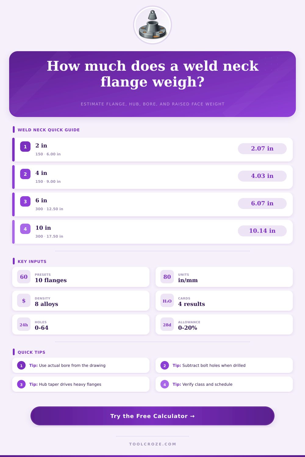
Choose a common weld neck flange scenario. Presets are practical estimating values; confirm final dimensions against the project standard or drawing.
| Preset | Nominal size | Class | Approx OD | Typical bore |
|---|---|---|---|---|
| NPS 2 Class 150 | 2 in | 150 | 6.00 in | 2.07 in |
| NPS 4 Class 150 | 4 in | 150 | 9.00 in | 4.03 in |
| NPS 6 Class 300 | 6 in | 300 | 12.50 in | 6.07 in |
| NPS 10 Class 300 | 10 in | 300 | 17.50 in | 10.14 in |
| Material | Density lb/in³ | Density g/cm³ | Use note |
|---|---|---|---|
| Carbon steel | 0.283 | 7.83 | Common forged weld neck flanges |
| Stainless steel | 0.289 | 8.00 | Corrosion resistant service |
| Duplex stainless | 0.283 | 7.82 | High strength corrosion service |
| Nickel alloy | 0.296 | 8.19 | High temperature or sour service |
| Volume item | Model used | Added or deducted | Check point |
|---|---|---|---|
| Flange body | Outer cylinder minus bore | Added | Uses OD and flange thickness |
| Tapered hub | Frustum minus bore cylinder | Added | Uses base OD, small OD, and hub length |
| Raised face | Short ring above bore | Added | Use zero height for flat face |
| Bolt holes | Hole cylinder through flange | Deducted | Applies to flange thickness only |
| Field input | Usually from | Common mistake | Estimator note |
|---|---|---|---|
| Bore | Pipe schedule or drawing | Using pipe OD as bore | Pipe OD may match small hub OD, not the open bore |
| Raised face | Flange standard | Counting full OD | Only the raised gasket land is added |
| Hub length | Forging drawing | Including flange thickness | Enter only hub beyond the flange body |
| Density | MTR or alloy table | Using carbon steel for all alloys | Nickel and stainless can shift lift weight |
Weld neck flange are used in environments where the pressure and vibration is present, as well as in environments where a long service life for the flanges is required. Weld neck flanges has a specific shape that includes a tapered hub. The tapered hub is used to distribute any mechanical load that are placed upon the weld neck flange.
Furthermore, the tapered hub prevents any area of concentrated stress upon the weld neck flange. However, because the tapered hub is included as part of the weld neck flange, the component of the flange also becomes significant in relation to the total weight of the weld neck flange. This weight of the weld neck flange is a factor in the shipping of the weld neck flange, the rigging of the weld neck flange, and the design of the structural steel that may support those flange.
How to Calculate the Weight of a Weld Neck Flange
In order to estimate the weight of the weld neck flange, one can calculate the weight of each of the individual components of the weld neck flange, and each of those individual weight can be added or subtracted according to the geometry of the weld neck flange itself. Even small alteration to the dimensions of the weld neck flange will impact the total weight of that component, which can impact the lift plan. To calculate the weight of the weld neck flange, several different dimension of the component are considered.
The outside diameter of the weld neck flange will determine the size of the ring of the flange that bolt to another flange. The thickness of the weld neck flange provide resistance against the internal pressure of the system. The bore of the weld neck flange must match the pipe schedule of the system in which the flange is to be installed.
The raised face of the flange include the amount of metal that forms a ring upon the weld neck flange to assist in the even seating of the gasket between mating flange. The bolt holes within the raised face include the amount of metal that the drilling of those hole removes from the weld neck flange. The dimensions of the hub are important on any weld neck flange that is larger than a certain size.
The dimensions of the weld neck flange that are obtained from the drawing of the component are typically already adjusted for the pressure class and the facing type of the weld neck flange. The material of the weld neck flange can have an impact upon the way in which the total weight is calculated. For instance, if the weld neck flange is made of carbon steel, the density of that material is known, and the cost of that material is known and relatively low.
However, if the weld neck flange is made of stainless steel or a nickel alloy, the density of the metal will be