⚡ Transformer Winding Wire Gauge Calculator
Calculate the correct AWG or SWG wire gauge for primary and secondary transformer windings
| AWG | Diameter (mm) | Diameter (in) | Cross Section (mm²) | Max Current (A)* | Resistance (Ω/m) | Resistance (Ω/ft) |
|---|---|---|---|---|---|---|
| 14 AWG | 1.628 | 0.0641 | 2.081 | 5.9 | 0.00832 | 0.00253 |
| 16 AWG | 1.291 | 0.0508 | 1.309 | 3.7 | 0.01320 | 0.00402 |
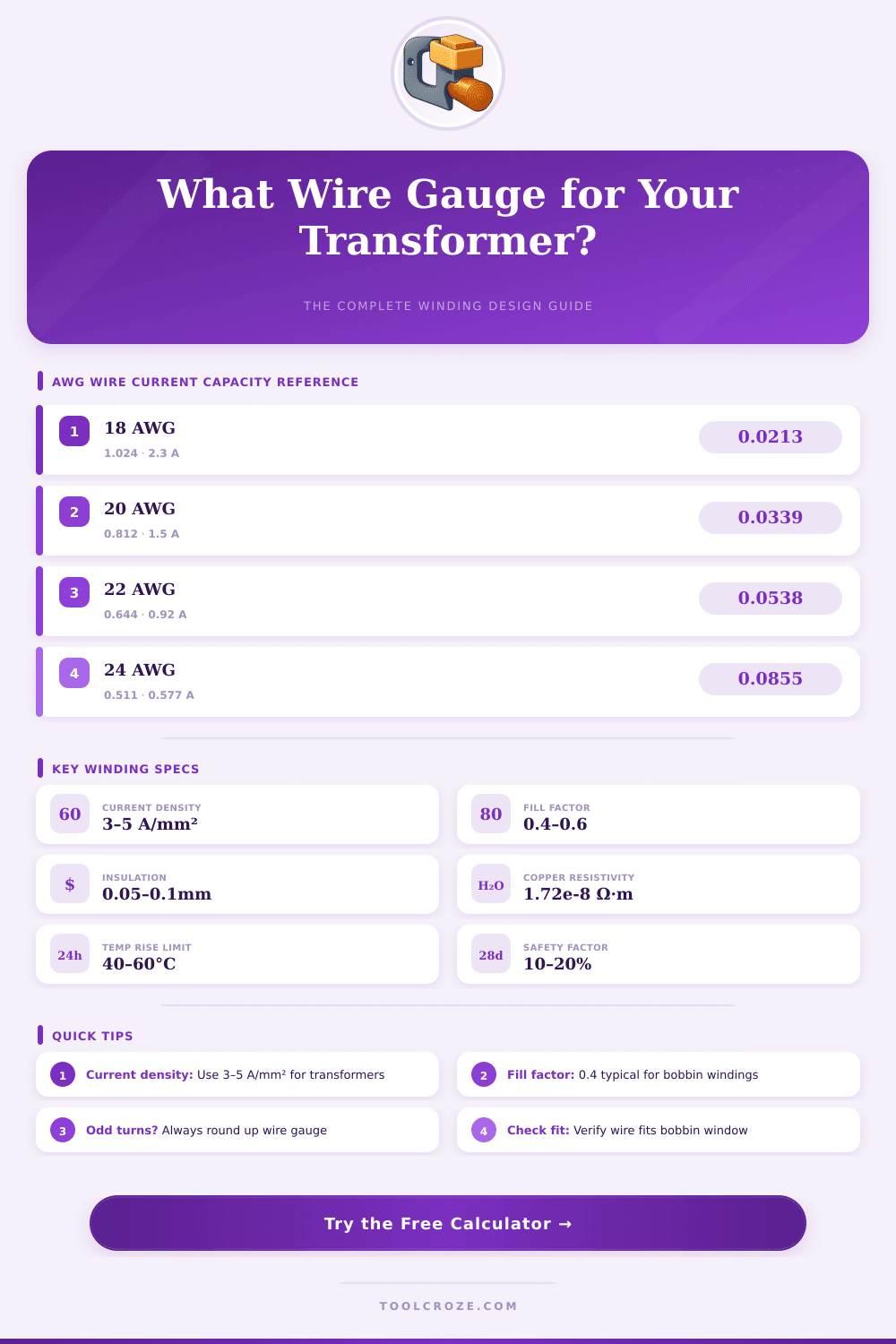
| 18 AWG | 1.024 | 0.0403 | 0.823 | 2.3 | 0.02100 | 0.00640 |
| 20 AWG | 0.812 | 0.0320 | 0.518 | 1.5 | 0.03340 | 0.01020 |
| 22 AWG | 0.644 | 0.0253 | 0.326 | 0.92 | 0.05310 | 0.01620 |
| 24 AWG | 0.511 | 0.0201 | 0.205 | 0.577 | 0.08420 | 0.02567 |
| 26 AWG | 0.405 | 0.0159 | 0.129 | 0.361 | 0.13380 | 0.04079 |
| 28 AWG | 0.321 | 0.0126 | 0.0810 | 0.226 | 0.21280 | 0.06487 |
| 30 AWG | 0.255 | 0.0100 | 0.0507 | 0.142 | 0.33890 | 0.10330 |
| 32 AWG | 0.202 | 0.0079 | 0.0320 | 0.091 | 0.53820 | 0.16410 |
| 34 AWG | 0.160 | 0.0063 | 0.0201 | 0.0577 | 0.85540 | 0.26080 |
| 36 AWG | 0.127 | 0.0050 | 0.0127 | 0.0361 | 1.3590 | 0.41430 |
| Core Type | Bmax (Tesla) | Typical T/V (50Hz) | Typical T/V (60Hz) | Fill Factor | Best For |
|---|---|---|---|---|---|
| E-I Laminated | 1.1 – 1.3 | 45 – 55 | 38 – 46 | 0.35 – 0.45 | General purpose, 10–500VA |
| Toroidal | 1.3 – 1.5 | 40 – 50 | 33 – 42 | 0.50 – 0.65 | Audio, low EMI, 10–1000VA |
| U-I Laminated | 1.0 – 1.2 | 48 – 58 | 40 – 48 | 0.35 – 0.42 | High voltage, 50–1000VA |
| Ferrite (SMPS) | 0.3 – 0.4 | N/A (kHz) | N/A (kHz) | 0.25 – 0.35 | Switch-mode, <100W |
| Powdered Iron | 0.6 – 0.8 | N/A (kHz) | N/A (kHz) | 0.30 – 0.40 | Inductors, RF transformers |
| Application | Primary V | Secondary V | VA Rating | Pri AWG | Sec AWG | Core Size (cm²) |
|---|---|---|---|---|---|---|
| Small Power Supply | 120V | 12V | 10 VA | 28 AWG | 22 AWG | 1.5–2.0 |
| Medium Power Supply | 120V | 24V | 50 VA | 24 AWG | 20 AWG | 3.5–5.0 |
| Large Power Supply | 120V | 12V | 100 VA | 22 AWG | 16 AWG | 6.0–8.0 |
| Audio Output | 8 Ω load | 600 Ω | 10 VA | 26 AWG | 30 AWG | 2.0–3.0 |
| Tube Amp HV | 120V | 300V | 75 VA | 24 AWG | 26 AWG | 5.0–7.0 |
| Doorbell/Low VA | 120V | 16V | 5 VA | 30 AWG | 26 AWG | 1.0–1.5 |
Election of the right Wire rating for the Winding of a Transformer is an important stage. The thickness of the Wire shows whether it is narrow or broad. One sorts the wires by its cross-section area and each gets its own rating.
Those numbers follow either the Standard Wire Rating (SWG) or the American Wire Rating (AWG). The chosen rating for the Winding relates to the current needs of the Transformer and its current density.
How to Choose the Right Wire Size for a Transformer
Current density is the main factor, when dealing about the maximum current that the Transformer can carry without danger. For each square millimeter one suggests around 2.565 ampere. If one goes past that value, the heat in the Transformer grows too much.
Less high density helps to keep everything cool, but it adds to the weight. Like this one must care abuot that balance.
Wires need to be quite big, so that the current through them does not warm too much and melt its coating, which could cause shorts in the Winding. Here is the basic thought for choosing a rating. The rating of Wire for a Transformer Winding depends on the volt-ampere rank of the device.
Also the number of coils, the kind of core and the used current affect the size of the Wire.
For a practical example, during building of a 5-ampere Transformer, 16-gauge copper Wire works for the Winding. In internal Transformers the Wire ratings range from 16 AWG until 52 AWG, according to the use. The coating on those wires usually lasts around 155 degrees Celsius.
Usually one uses coated copper wires, that match the grade for Transformer Windings.
It is possible to find online tools, that help with this. A company called Micro Digital offers an online Calculator for Transformer Windings. It allows you to estimate the right SWG or AWG, so that the Wire can carry the needed current for a certain target.
Some programs for design also let engineers change the ratings of wires, to improve the result or reduce cost, commonly by means of menus four building Windings.
Practical tips for working with an already finished Transformer are to wrap ten turns above the existing coils and estimate the voltage difference. That shows the ratio of turns to voltage, which helps to plan the other parts of the design. Also sold are Transformer kits with pre-rolled basic coils, that include notes about the needed turns for secondary and what rating of Wire to use.
Another way to understand all this is to take apart a simple Transformer and study it carefully, noting the ratings of wires, kinds of coatings, turns per layer andother small details. These studies are actually rich in information.