To perform TIG welding, it is necessary to ensure that the molten weld pool are isolated from a air. If TIG welding operations does not ensure that the weld pool is isolated from air, the welding operation will fail. If the shielding gas coverage provided during the welding operation is incorrect, weld failures may occur in that the weld may contain porosity, the tungsten electrode may turn black, or the weld may fail with a crack after several weeks of the welding processes.
The flow chart that is provided in this welding technology explain the various decisions that a welder must make in the decision of which shielding gas to use during the welding process, and at what flow rates of that gas. Welders often use pure argon gas in the welding process. Argon gas is a stable gas that works with various metals; it readily forms an electric arc between the tungsten electrode and the metal to be welded, it maintains that arc whether using AC or DC electrical current, and it welds well with metals like steel, stainless steel, and even aluminum.
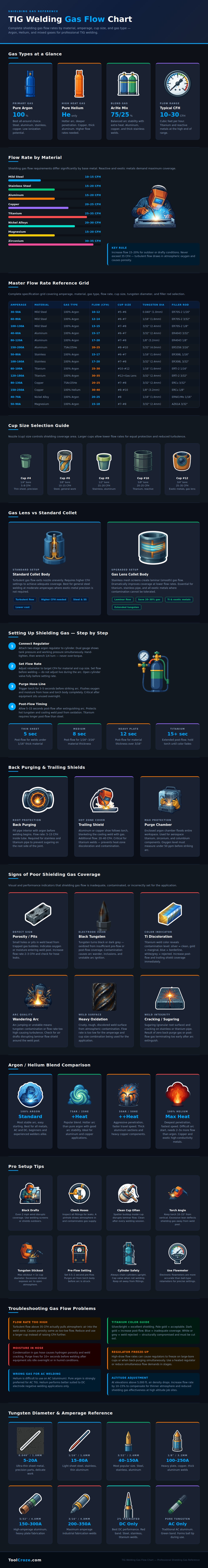
How to Choose Shielding Gas and Flow Rates for TIG Welding
Argon gas may be mixed with helium gas, however, if the metal to be welded is more thicker in composition or conducts heat more readily away from the weld zone. Helium gas increase the temperature of the electric arc between the welding electrode and the weld zone, but it reduces the stability of the electric arc; thus, a welder must use higher flow rate of the argon/helium gas mix when welding with helium to compensate for the reduced stability. Reactive metals, such as metals like titanium and zirconium, require more shielding gas than metals like mild steel because the presence of oxygen in air may ruin the weld if that oxygen reaches the hot zone of the metal being welded.
Because oxygen can ruin the weld on reactive metals, reactive metals must have larger welding cups, larger lenses in the welding torch that direct the shielding gas towards the weld zone, and longer periods of time after welding is completed during which the shielding gas covers the hot weld bead. These requirement for reactive metals are shown in the flow chart provided with the technology. The cup size for welding torches affect the shielding gas’ coverage of the weld zone.
A weld torch with a larger cup will disperse the shielding gas over a greater area than a torch with a small welding cup. Consequently, a welding torch with a larger nozzle will allow for a lower flow rate of shielding gas to provide the same coverage as a welding torch with a small welding cup. In contrast, a welding torch with a smaller welding cup may be used on a metal component that is thick in composition.
Under these conditions, the weld torch must push the shielding gas at a higher flow rate in order to overcome the increased resistance to the flow of the shielding gas that is created by the narrow opening of the welding torch. These welding torch cup sizes and their relationship to the flow rates of the shielding gas are represented within the provided flow chart. Gas lenses contain a mesh screen that straightens the flow of the shielding gas as it exit the welding torch.
The result of including this mesh screen is that the shielding gas exits the welding torch in laminar (smooth) flow of gas. These laminar flows allow for a reduction in the flow rate of the shielding gas that is required to protect the tungsten electrode and the weld pool. Gas lenses are often used with metals that are prone to forming a contaminated joint with the weld metal, such as titanium metal or stainless steel; the cost of forming a contaminated joint is high, so using a gas lens is one means of avoiding the formation of that contaminant joint.
To use the technology as described, it is necessary to follow a specific sequence of steps. First, the welder must connect the shielding gas regulator to the welding torch; next, the welder must fully open the cylinder of the shielding gas; after that, the welder can adjust the flow rate of the shielding gas; and then the welder must perform a quick purge of the shielding gas through the welding torch to ensure that air is not within the welding torch hose. Following the welding process, post-flow of the shielding gas is required to protect the newly formed hot tungsten and hot weld bead.
Thicker welds will require more time for post-flow than thin welds to protect the weld bead. Common problems in the welding process may result from incorrect settings of the shielding gas or from drafts in the welding room. If the flow rate of the shielding gas is too high, the high flow rates can create turbulence within the welding torch in a manner that pulls air into the weld zone.
If the flow rate of the shielding gas is too low, the shielding gas may not cover the molten weld pool. These errors in the welding process can result in various problems in the weld, such as pitting, sugaring, or black tungsten. Each of these problems is represented in the flow chart.
The main purpose of the flow chart is to allow welders to avoid the need for mental math calculations during the welding process. By looking at the metal that is to be welded and the amperage range of the welding process, a welder can refer to the flow chart to determine if larger welding cups, gas lenses, or a shielding gas that includes helium should be utilize in the welding process. Welders who use the flow chart have more clarity in their welding process, which helps them to control the welding torch and weld process to ensure that the weld is free of error.
