🔥 TIG Welding Gas Flow Rate Calculator
Estimate torch shielding flow, cup exit velocity, purge fill time, post-flow, and bottle runtime for common TIG materials, gas mixes, and joint conditions.
📌 Weld Presets
⚙ Flow Inputs
🎯 Flow Results
📈 Material and Gas Comparison
📊 Reference Tables
| Material | Target Velocity | Typical Torch Flow | Purge Note |
|---|---|---|---|
| Mild steel | 30 ft/s | 12-18 CFH | Usually none |
| 304 stainless | 28 ft/s | 12-20 CFH | Root purge often used |
| 6061 aluminum | 23 ft/s | 14-24 CFH | No purge, larger cup |
| Titanium Grade 2 | 20 ft/s | 18-30 CFH | Trailing or chamber purge |
| Inconel 625 | 26 ft/s | 14-22 CFH | Root purge preferred |
| Copper C110 | 24 ft/s | 16-28 CFH | Helium mix is common |
| Cup | Diameter | Area | Argon Bench Range |
|---|---|---|---|
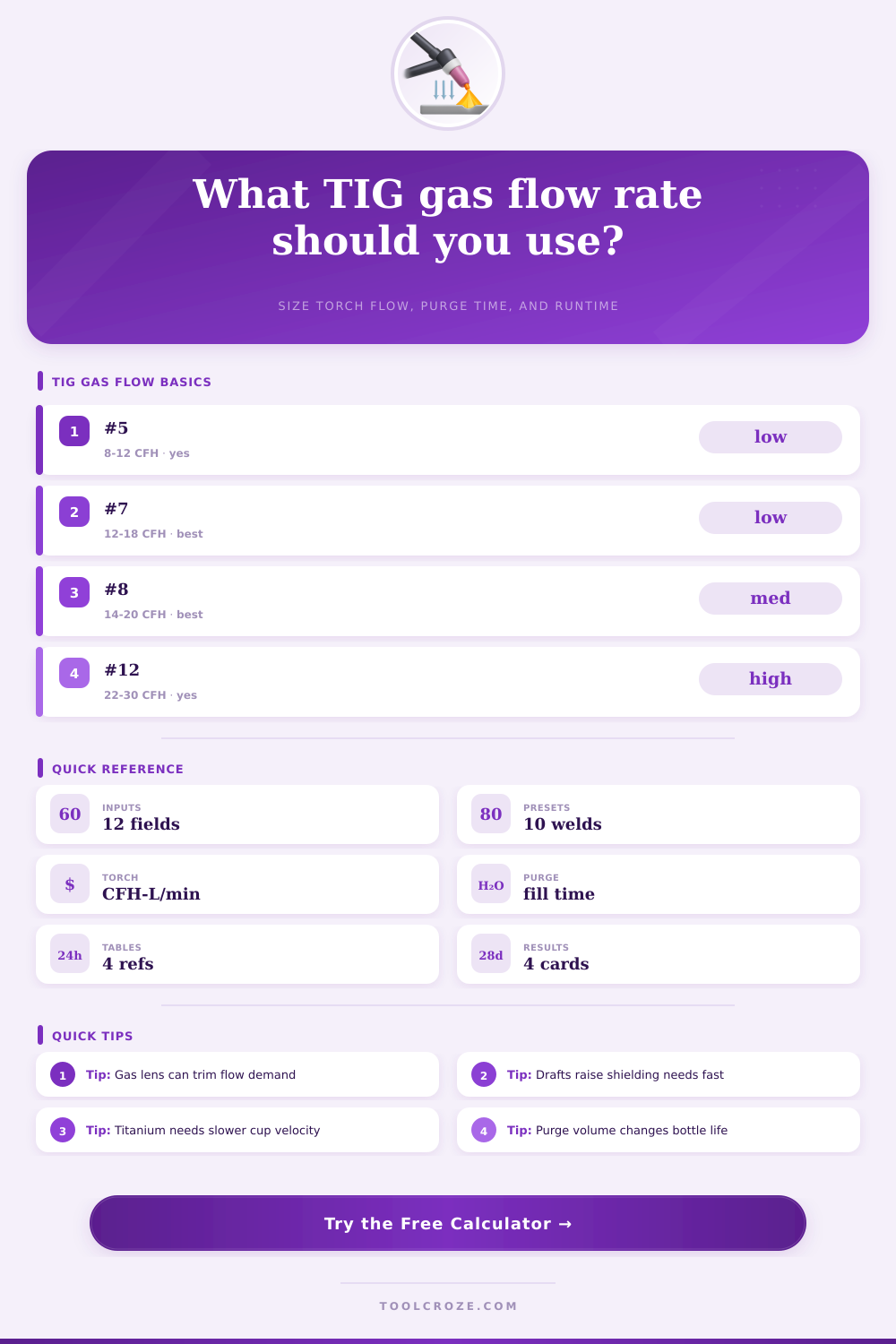
| #5 | 0.313 in | 0.077 in2 | 8-12 CFH |
| #6 | 0.375 in | 0.110 in2 | 10-14 CFH |
| #7 | 0.438 in | 0.151 in2 | 12-18 CFH |
| #8 | 0.500 in | 0.196 in2 | 14-20 CFH |
| #10 | 0.625 in | 0.307 in2 | 18-24 CFH |
| #12 | 0.750 in | 0.442 in2 | 22-30 CFH |
| Gas Mix | Flow Factor | Arc Behavior | Common Use |
|---|---|---|---|
| 100% argon | 1.00x | Stable, soft plume | General TIG |
| Ar-He 75/25 | 1.15x | Hotter puddle | Thicker aluminum |
| Ar-He 50/50 | 1.35x | High heat input | Copper, heavy section |
| 100% helium | 1.80x | Very light gas | Large heat sink jobs |
| Ar-H2 95/5 | 0.92x | Fluid stainless puddle | Austenitic stainless only |
| Ar-H2 98/2 | 0.96x | Milder H2 boost | Light stainless tube |
| Usable Gas | At 15 CFH | At 20 CFH | At 25 CFH |
|---|---|---|---|
| 80 ft3 | 320 min | 240 min | 192 min |
| 125 ft3 | 500 min | 375 min | 300 min |
| 150 ft3 | 600 min | 450 min | 360 min |
| 250 ft3 | 1000 min | 750 min | 600 min |
💡 Shop Notes
Use this calculator to balance TIG cup size, gas mix, draft, purge volume, and post-flow timing so shielding stays stable without wasting cylinder gas on stainless, aluminum, titanium, or steel welds.
Shielding gas are one of the critical component of TIG welding. Shielding gas prevent oxidation of the stainless steel by maintaining a protective layer between the weld and an atmosphere. If the flow rate of the shielding gas are too low, air will enter the weld area and cause oxidation on the stainless steel.
If the flow rate of the shielding gas is too high, the shielding gas will create turbulence in the weld area and waste shielding gas from the cylinders. The flow rate of the shielding gas must be manage to ensure that the shielding gas creates a stable plume around the weld. The shielding gas forms a plume or bubbles of inert gas around the welding arc.
How to Use Shielding Gas in TIG Welding
Argon is the shielding gas of choice because argon is denser than air. Because argon is denser than air, argon can sit on top of the weld pool and push the oxygen away from the weld area. The velocity of the shielding gas is also essential.
If the shielding gas velocity is too slow for the welding position, draft will enter the weld area. If the shielding gas velocity is too fast, the shielding gas will become turbulent and will pull the atmosphere into the weld pool. The size of the ceramic cup will affect the shielding gas velocity.
A larger ceramic cup require a higher shielding gas flow rate to maintain the same shielding gas velocity as a smaller ceramic cup. A #8 ceramic cup has a larger opening than a #5 ceramic cup. Therefore, more shielding gas are required for a #8 ceramic cup to maintain the same shielding gas velocity as a #5 ceramic cup.
Drafts in the workplace can interfere with the shielding gas. The drafts can blow the shielding gas sideways out of the weld area. If the shielding gas is blown sideways out of the weld area, the weld will be exposed to oxygen.
To prevent this from happening, it may be necessary to increase the shielding gas flow rate when working in area with drafts. Another factor that can impact shielding gas is the tungsten stickout. The tungsten stickout is the distance from the tip of the tungsten electrode to the edge of the ceramic cup.
If the tungsten stickout is increased, the shielding gas will have to travel a longer distance to protect the weld. A longer distance require a higher flow rate of shielding gas. The shielding gas can be mix with other gases.
Pure argon is the most common shielding gas. If any amount of helium is added to the argon, the shielding gas will behave different. Helium is lighter than argon.
Therefore, if a mixture of argon and helium is used, the shielding gas will rise more quick out of the weld pool. Higher flow rate of the argon-helium mixture will be necessary to maintain shielding of the weld. Another commonly used shielding gas mixture consist of hydrogen and argon.
When used on stainless steel, the hydrogen will change the behavior of the weld puddle. In this situation, the welder will have to adjust the shielding gas velocity to avoid cause cracking of the weld shield. Back purging of the weld is used to protect the backside of the weld from being oxidized.
Back purging is critical for stainless steel and titanium because the oxidation of these metal on the backside of the weld will reduce the corrosion resistance of the metal. To back purge a weld, the welder will have to flood the interior of the pipe with shielding gas. A significant amount of shielding gas will be consumed during a back purge of the weld.
After the welding is complete, post-flow of shielding gas will be necessary to protect the tungsten electrode and the weld crater. The welder will have to adjust the post-flow time according to the size of the electrode and the amperage of the weld. Common mistake are made when managing the shielding gas.
One of the most common mistakes is increasing the shielding gas flow rate to fix the problem of a poor arc start. The problem may not be the shielding gas but the contaminated ceramic cup or the incorrect tungsten stickout. Another common mistake is failing to use the gas lens diffuser.
The gas lens diffuser will straighten the stream of shielding gas. Depending on the shielding gas used, the gas lens can reduce the amount of shielding gas needed by ten percent. It does this by reducing the turbulence in the shielding gas stream.
Another consideration regarding the shielding gas cylinder is the total runtime of the cylinder. A standard shielding gas cylinder holds 125 cubic feet of gas. Based off the flow rate of the shielding gas, the welding machine will provide a specific amount of welding time.
Using higher flow rates of shielding gas will use the gas in the cylinder more quick. Using shielding gas mixtures that contain helium will use the shielding gas more quick due to the higher flow rates required of this shielding gas mixture. A specific amount of the shielding gas in the cylinder can be used instead of the pressure of the gas in the cylinder.
This is because the amount of shielding gas will naturaly decrease as the cylinder of shielding gas is emptied. If the flow of the shielding gas is managed correctly, TIG welding will produce weld that dont require grinding and will use the shielding gas more efficient.