The low grinding sound you hear when working under load is most frequently caused by a thrust bearing that wasn’t quite the right size for the task. A thrust bearing are located on a shaft near its end. They’re there to absorbs the push or pull as equipment attempts to move everything out of alignment. Selecting too small a dimension cause the entire system to fight itself and wear out faster than normal, eventually resulting in an unscheduled shutdown.
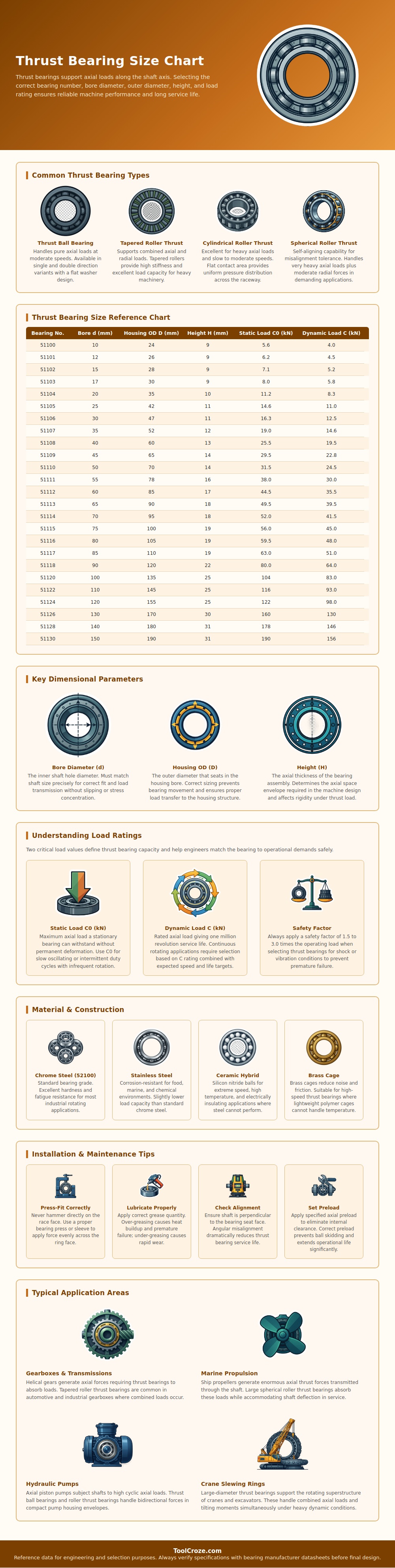
But this is all laid out on chart below. The bare bones are what you realy want to know. You’ll find the outside diameter of the housing it fits in, the inside diameter (bore), and total length. There is also two loading numbers. These specify how much stress a bearing can takes while spinning versus just sitting there.
How to Choose the Right Thrust Bearing
If you cross over one row you instantly see if a particular model are even going to fit physically into your housing and on your shaft. Compare those loads to the actual loads you create in your application. That’s why you don’t have to do so much trial and error, one look at a chart like this saves it.
The dynamic load rating is what most folks pay attention to since this rating applies to “normal” running conditions. But when a machine turn extremely slow or is sitting stationary for extended periods of time, the static rating becomes equally important. Static means simply how much weight can be applied to a bearing without developing flat spots. Even if a bearing look okay on paper, the static load will cause flat spots if it exceeds its static limit.
The gap between these two number determines how close to the published limit you wish to run versus having additional margin. The same principle applies to material selection. For most industrial applications, you can get by with chrome steel, it balance hardness and cost. If chemicals or moisture come into play, you need stainless, which isn’t quite as strong, but will last longer. When you start moving faster or need electrical insulation, ceramic hybrids are the way to go. Most heavier thrust bearings uses brass for the cage, which lowers friction at high speeds while maintaining proper spacing between the rolling element. There’s no one best answer here, just solutions to various constraints found in actual equipment.
That precisely selected bearing will only reach its full rated life if you develop an installation habit. Lubrication is right; preload is correct; it’s pressed-on squarely. This is more important than most operators knows. The edge loading of a slightly tilted install was not in the load ratings. Too-greasy keeps it hot, too-sparse allows metal-to-metal contact in hours. With a square, you can check that shaft is square to housing face in a minute. However, you can still miss the misalignment that silently cuts service life in half.
A crane with its large slewing ring works on the same principle. Look at hydraulic pumps, gear boxes, marine drives, all of them asks the bearing to handle some axial load as the shaft continues to rotate or the structure continues to swing. The size chart just translates that force for you so you have something to compare based off what’s available.
It’s one thing to know there are different measurements and another to understand which should recieve priority attention on your specific machine. Once you use the chart as a decision-making tool instead of a menu, selecting the right thrust bearing won’t feel like guessing anymore. In other words, it will begin to look like plain ole’ engineering, it should of been easier.
