Taper Per Foot Calculator
Calculate taper per foot, taper per inch, included angle, compound angle, setover, slope ratio, and inspection readings from large and small diameters.
⚙Workshop presets
📏Taper setup inputs
Calculated taper setup
🔧Material and setup grid
📊Standard taper reference
| Standard | Taper per foot | Half angle | Typical use |
|---|---|---|---|
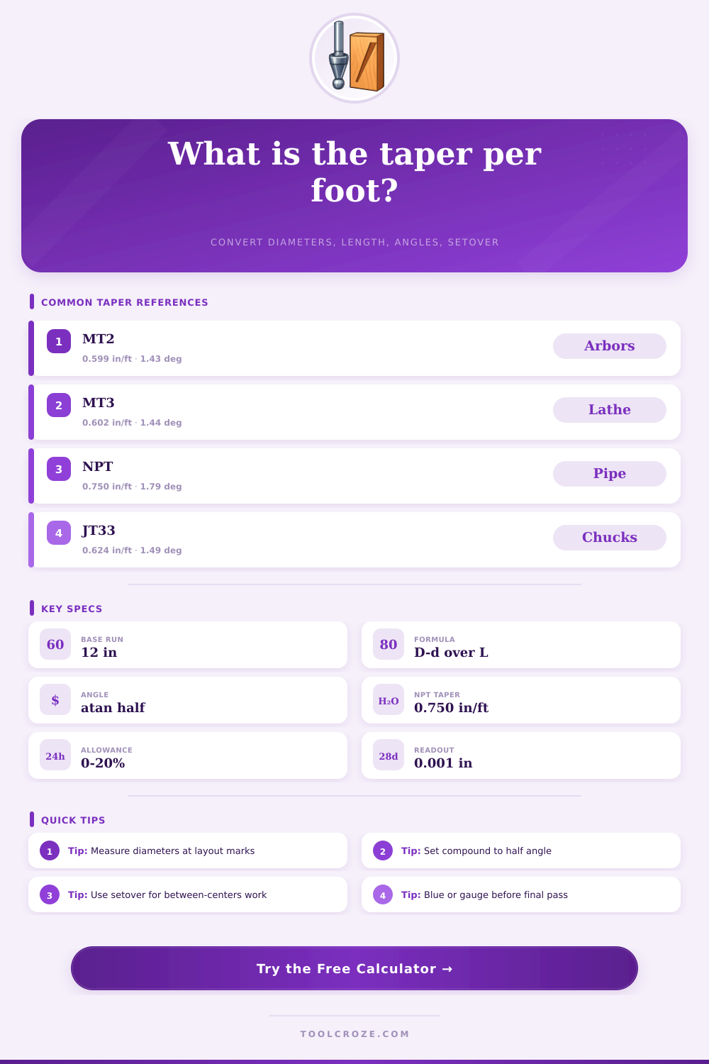
| Morse taper 1 | 0.5986 in/ft | 1.4287° | Small centers, drill sleeves |
| Morse taper 2 | 0.5994 in/ft | 1.4307° | Tailstocks, drill chucks, arbors |
| Morse taper 3 | 0.6024 in/ft | 1.4377° | Lathe spindles and mill tooling |
| Jacobs taper 33 | 0.6240 in/ft | 1.4890° | Drill chuck mounting seats |
| National pipe taper | 0.7500 in/ft | 1.7899° | NPT external and internal pipe threads |
| Taper pin reamer | 0.2500 in/ft | 0.5968° | Standard taper pins and reamed holes |
🧮Formula and setup reference
| Calculation | Formula | Use it for | Setup note |
|---|---|---|---|
| Taper per foot | (Large dia. – small dia.) × 12 / length | Print callouts and taper standards | Based on diameter change, not radius |
| Compound angle | atan((Large dia. – small dia.) / (2 × length)) | Lathe compound slide setting | Angle is from spindle centerline |
| Included angle | 2 × compound angle | Cone angle and CAD modeling | Some drawings list included angle |
| Tailstock setover | Center distance × diameter change / (2 × length) | Long tapers between centers | Offset tailstock by radial amount |
| Sine bar rise | Sine length × sin(compound angle) | Inspection, grinding, gauge setup | Use the half angle for one side |
🛠Material finishing reference
| Material | Finish SFM range | Suggested last pass | Taper fit caution |
|---|---|---|---|
| 6061 aluminum | 200-350 SFM | 0.002-0.006 in | Can gall; use lubricant for test fits |
| Mild steel | 90-140 SFM | 0.001-0.004 in | Blue fit before removing final tenths |
| 303 stainless | 50-90 SFM | 0.001-0.003 in | Keep tool sharp to avoid work hardening |
| Free-machining brass | 160-250 SFM | 0.001-0.004 in | Check spring-free tool geometry |
| Acetal plastic | 250-500 SFM | 0.003-0.010 in | Allow for heat growth during measuring |
🔍Inspection readings reference
| Taper per foot | Diameter change per inch | Half angle | Shop interpretation |
|---|---|---|---|
| 0.250 in/ft | 0.0208 in/in | 0.5968° | Shallow taper pin style |
| 0.500 in/ft | 0.0417 in/in | 1.1935° | Moderate locking taper |
| 0.600 in/ft | 0.0500 in/in | 1.4321° | Typical Morse-style taper |
| 0.750 in/ft | 0.0625 in/in | 1.7899° | National pipe taper |
| 1.000 in/ft | 0.0833 in/in | 2.3859° | Steeper wedge or fixture taper |
💡Shop calculation tips
Here’s an example: You pick up a shaft at the lathe whose intended use require it to fit inside some other part. A drawing specifies exact taper for each foot of bore. This is one of those times when intuition isn’t going to help. Because the geometry you’re working with is obscured by hiding behind your fingers. Your eye can’t see the slope; there’s no option but faith in the mathematics.
Enter big and little diameters and length between two on the calculator and let it do the heavy lifting. It transforms abstractions into a plan that works in real world. Those three values determine the gauge change you’ll observe across a brief section of the component. They also determines the setover distance on your tailstock and half angle for your compound slide.
How to Machine Tapers Correctly
So most machinists begin by measuring both small and large ends. Simple enough until you learn that how accurately you can measure is only half the battle. Where you measure is also important. Take a measurement across the workpiece at a deburred edge or a chamfer and the apparent taper will be completely different than what you expect. You need to take your measurement at true cylindrical surfaces that has been clearly laid out. It’s a small thing, but it makes the difference between a fit that slips and one that jams.
The same holds for length along the axis since this establishes the run against which the rise are measured. A small error in taking length measurement immediately carries through to the angle measurement. This alter your compound setting enough to throw off the final pass. The half angle is typically the one used when setting up manually on the lathe. That’s the angle from the surface back to the centerline. Set it to that exact amount on your compound slide.
On many drawings, they’ll put down the included angle. That’s total cone angle from side to side. If you just take the included angle and throw it directly onto your compound you’ll end up cutting a taper twice as steep as desired. And that actualy happens more often than people care to admit. The calculator clearly separates out those two numbers so there won’t be any confusion over which number goes where: into the digital readout or the sine plate.
For longer tapers beyond the range of movement of the compound slide, the setover of the tailstock is the way to go. Depending off how far apart the centers are, the tool calculate exactly how far to offset. Plunge straight away with no adjustments necessary during the cut.
If you have a custom taper for which you want to calculate RPMs and feed rate, then having some idea about what is common will help you check if your custom calculation seems reasonable. 6 inches per foot. 75 inches per foot. Why do we have those? They give us a reliable friction fit on thousands of machine over decades of machine building. Even if you’re machining something that doesn’t fit into one of these categories, the calculator can still tell you the ratio of the slope and surface speed. You can then check this against the material properties to cross-reference your cutting parameters. Mild steel will behave differently than 6061 aluminum regarding tool wear and heat generation on an angle cut.
If you take a finishing taper pass at too high a surface speed, you might find your tool digs in or starts chattering when you didn’t expected. Where it’s really valuable for me is when you’re trying to confirm the work but haven’t committed to the final fit yet. I can measure a small gauge section rather than going all the way down the length; that may or may not be practical. But you’ll get exact data on how much the diameter should of changed across whatever distance you measured.
So if you read the caliper and find that it’s just a hair oversized, you know that the angle must be right because the predicted difference in diameter was equal to what you found with the caliper. That makes a very complicated shape check into a simple straight-line measurement. Rough cut, gauge a span, adjust as needed, and leave a few thousandths for finishing.
Machining tapers then is really all about respecting this change in diameter to length ratio. The numbers on the screen are just real-world measurements turned into values we can use. When we know what those outputs represent it’s no longer the math but rather a guide and once we’ve dialed in the CNC parameters, or moved the tailstock out for an offset, or selected the angle…we have confidence in our setting. Geometry is correct and now the rest falls into place. Everything from that first layout mark onward will follow.