Stitch Weld Calculator
Calculate intermittent stitch weld length, gap, pitch, number of stitches, effective weld length, coverage, open panel length, arc time, and heat input reduction versus a continuous weld.
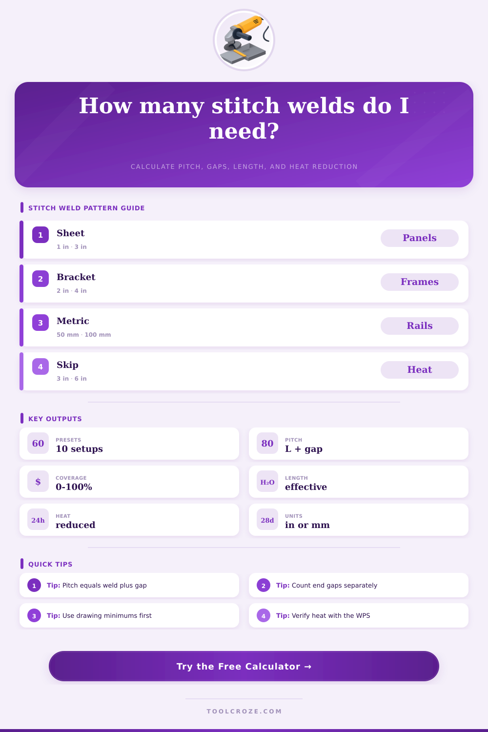
Choose a common intermittent weld pattern. Presets fill panel length, stitch length, gap, count mode, heat input, travel speed, and end spacing.
| Pattern basis | Formula | What it means | Watch point |
|---|---|---|---|
| Pitch | stitch length + clear gap | Repeating center-to-start distance for one stitch cycle. | Some drawings define pitch center-to-center; confirm notation. |
| Auto-fit count | floor((usable length + gap) / pitch) | Maximum full stitches that fit after end margins. | Short remainder may need adjusted end spacing. |
| Effective length | stitch length x count x weld lines | Total welded length for strength and heat comparison. | Do not include unwelded gaps in weld strength. |
| Heat reduction | 1 - effective length / continuous length | Approximate heat reduction versus welding the same seam solid. | Starts and stops may add local heat. |
| Typical setup | Stitch length | Gap range | Planning use |
|---|---|---|---|
| Thin sheet panels | 0.5 to 1.5 in | 2 to 5 in | Limit distortion while holding light sheet seams. |
| Frames and brackets | 1.5 to 3 in | 3 to 8 in | Balance attachment length with heat control. |
| Stiffener to plate | 2 to 4 in | 4 to 10 in | Distribute welds along a long member. |
| Metric fabrication | 25 to 75 mm | 75 to 200 mm | Use metric drawing pitch and weld length directly. |
Stitch welding is an welding method that allows you to place weld in short segments with gaps between each segment. You may wish to use stitch welding in place of a continuous weld because stitch welding allow you to control the heat and time that your metal component are exposed to and allows for better control of metal distortion. Continuous weld expose a panel or frame to heat over a longer period.
Instead, stitch welding introduces less total heat and arc time into the metal components. By entering information about your panel, the size of the stitches, the size of the gaps between each stitch, the weld process, and the layout you would like to use for your weld, the calculator will give you an idea of the number of stitches you will have to perform, the amount of metal that you will deposit into the components, and the amount of heat that you will save by using stitch welding as opposed to a continuous weld. The placement of the stitches and the length of each stitch are two of the most important detail to consider with stitch welding.
Stitch Welding and the Weld Calculator
Using short stitches with large gaps between each weld will expose the metal components to less heat than using long stitches with small gaps between the welds. This might be an advantage if you are welding thin sheet metal component or metal frames. Using long stitches with a small gap between each weld will allow your metal to be welded in a way that is close to the performance of a continuous weld.
This might be necessary if the metal components must be able to handle vibration. Several different layout options is provided. The auto-fit mode will place as many full stitches as possible into your metal components.
Using the fixed count mode allow you to enter the number of stitches that you would like along your component. Using the centered mode will ensure that the stitch weld pattern is balanced along the ends of the component. Finally, the alternating mode will allow the weld pattern to be distributed between the two sides of the metal component to allow for better control of metal distortion.
One of the most important factor in stitch welding is the amount of heat that is input into the components. Each time the welder starts or stops welding, heat is added to the metal component. However, by reducing the total length of the weld, the total amount of heat that is given to the metal components is also reduced.
The calculator will ask for the voltage, the amperage, the travel speed of the welding head, and the arc efficiency of the welding process. Using these variable, the calculator can estimate how much heat will be saved if you use stitch welding as opposed to a continuous weld. This information can help to ensure that the metal components will not exceed the limits of their welding procedure specifications.
If the amount of heat that will be introduced into the components is very large, it is possible that there may not be enough weld length to allow for proper support of the metal components. If the amount of heat that will be introduced into the components is small, the stitch welding pattern is acting in a similar fashion to a continuous weld. In this case, the benefit to distortion control is likely to be very small.
The exact measurements for metal components are rarely perfect. The thickness of the metal may not be the same along each component. The fit-up of the components may not be perfect.
Furthermore, the drawings may use pitch notation instead of the length of the components to be welded. The tables located on the page provide the dimensions of various metal components including frames, sheet panels, stiffeners, and metric metal components. These tables can help you to understand the typical dimension of different metal components.
In addition, these tables can help to let you know if the size of the gaps between each stitch is very small relative to the length of the weld or if the gaps between each stitch are too large. A pattern allowance is included for the starts and stops of the weld. This factor is used in calculating the amount of weld that a welder may perform during the fabrication of metal components.
One of the most important factor to consider when performing stitch welding is the welding process that is to be used. Short-circuit MIG welding processes are faster and tend to generate less heat when welding thin metal components than flux-cored wire or stick welding processes. Flux-cored wire and stick welding processes tend to deposit a larger bead of metal into the component being welded.
This increases the amount of heat that is added to the metal component. The welding process selector allows for the welding process, voltage, amperage, and travel speed to be pre-loaded into the calculator. Each of these variable will impact the total amount of heat that is added to the component when using a stitch welding process.
For example, if the welding process is changed from MIG welding to stick welding, the total heat that is added to the component will increase even if the length of each stitch and the size of the gaps between each stitch remain the same. This information can help to quote jobs to customers or to determine whether stitch welding will provide the level of distortion control that is required of the metal components. When calculating the strength of the metal components that are to be welded together, it is important to use only the length of the weld that will actualy be welded, not the length of the metal component panels.
The gaps between each stitch of welding will not contribute to the strength of the component being welded. Thus, the total effective length of the component will be calculated by multiplying the length of each stitch by the number of stitches that will be made and the number of lines that will be welded together. This value can be compared to the total length of the metal component panels.
Furthermore, the estimate of the throat area of the weld allows one to have an idea of the cross-sectional area that will allow the weld to support the loads that are to be placed upon it. These calculations are not a replacement for engineering calculations of the strength of metal components but will help to avoid the error of considering the unwelded gaps of metal components to contribute to the metal strength. A few of the details of the weld pattern can be adjusted to meet the needs of the metal components.
For instance, end margins can prevent the weld pattern from encroaching upon the radius of the component. If the remainder of the length of the component after the last stitch is very large, it may be important to center the weld pattern along the component and adjust the size of the gaps between each stitch. Furthermore, if using an alternating weld pattern, it is important to indicate on the drawing of the metal components the side of the components upon which each weld will be performed.
Some warnings will display within the calculator indicating potential issues with the dimensions of the component or the weld pattern relative to the number of lines to be welded. Running the numbers for the weld pattern before striking an arc in the metal components provides value to the fabrication of those metal components. Knowing the amount of distortion that will occur during the welding of the components will allow you to plan for the distortion of those components.
Furthermore, knowing the arc time allows for better planning of the fabrication schedule. The length of the weld that will be performed can also be viewed to determine if it is a reasonable length for the metal components that are to be fabricated. By knowing each of these variable in advance, adjustments can be made to the gap between each weld, the length of each weld, and the welding process before any metal components are cut.
This will prevent any problems from being discovered after the metal components have been tacked together. You should of checked the dimensions first to avoid a mess.