
On the shelf you’ll find a bunch of steel tubing that’s identical in appearance but internally is very much not the same thing at all. Some are welded end to end, with a weld seam clearly visible along their full length. Others were never joined; they’re made from a single piece of heated iron that was simply pierced and cut into tube. Which one would you rather get? It makes a difference. The way these things are made determines how they behave under heat and pressure.
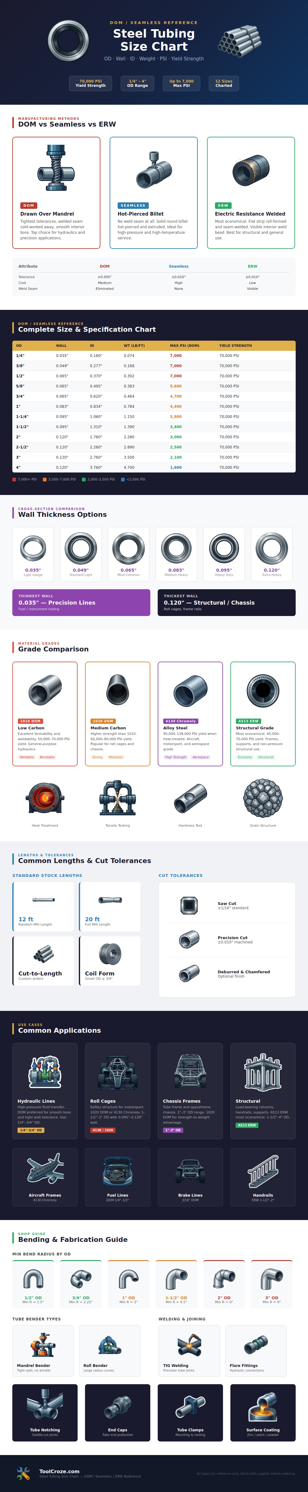
Here’s a chart that explains it (and compares the ERW and the seamless DOM process side by side) showing why tolerances vary so wildly between grades that share the same outer diameter.
How to Choose the Right Steel Tubing
This is seamless tubing. Starting with a hot billet, seamless tubing is pierced out to a hollow core. Because this method does not require welding, there are no weld seams anywhere in the piece of tubing. This makes it perfect for high temperature applications, as a weld joint could potentially weaken or fail.
Drawn Over Mandrel tubing results in incredibly tight wall thicknesses and smooth interior bores.
This is an electric resistance welded tube. This type of tube starts off as flat strips which are then electrically bonded together at their seam. E.R.W. Is formed into shape. Tube is the economical go-to guy for those jobs where precise tolerances aren’t critical but you need something that will get the job done. Cost is the main driver here; good enough is good enough for uses like a structural frame.
This is drawn over mandrel tubing. This process is known as a cold working operation. The tubing goes through a die, where an internal mandrel maintains the perfect shape and draws the tubing through. As a result, the bore on the inside is ultra-smooth and the wall thicknesses is very tight. Here, fluid dynamics are important. Think hydraulic systems and even the slightest bit of irregularity could mean seal failure or pressure spikes; D.O.M. Is the best option for these kinds of applications.
Selecting the right wall thickness requires thinking about the load rather than just the size. As the infographic shows, a quarter-inch tube with thin walls is much lighter per foot than one made from thick-walled material. But those lightweight qualities has their limits when it comes to buckling resistance and burst pressure. The table shows that as the outer diameter increases, the max PSI ratings also increase unless the wall thickness increases to match. That’s simply a function of geometry as a larger outside diameter means greater surface area for the inside pressure to act on.
When making a chassis frame or a roll cage, generally speaking, you want thicker walls such as a 10-20th of an inch, which gives you better resistance to collapsing under impact. For tubing for instruments and fuel lines you typically want thinner walls which can be more easly flared and bent without being prone to kinking.
But the grade of material does change the equation significantly. In the graphic above, I’ve shown a side by side look at low-carbon 1010 steel, medium-carbon 1020 and high-strength 4130 chromoly alloy. Low carbon is forgiving for the beginner who’s likely to burn through the metal or crack a tight radius bend. It bends easily and is easy to weld. Medium carbon has a better strength-to-weight ratio so it wins in applications such as chassis on automobiles. And then there’s chromoly, an altogether different beast because it has a massive yield strength when heat-treated properly, rivaling much thicker sections of mild steel. As a result, designers can use smaller diameters for high-performance suspension components and aircraft frames. You pay more for the alloy but you gain significant weight savings while not sacrificing any safety margin.
This also applies to fabrication methods. Big diameter tubing bends best when you have big radius clearances to prevent ovalization of the cross-section. Using a mandrel bender helps support the interior to maintain its integrity. The guide section states that a bend in a two inch tube should have a minimum bend radius of six inches. That allows the bend to maintain structural integrity. A mandrel bender also supports the inside of the pipe as it curves and prevents wrinkling or collapsing on the inner bend line.
Welds add their own variables with TIG being the cleanest joint for thin wall tubing while MIG is faster for heavier frame type structures. Notches must be done correctly to allow for maximum weld penetration. Maximum rigidity is gained when tubes meets fully at the intersection point.
In conclusion, selecting steel tubing is a compromise between weight, strength, ease of fabrication, and cost. Don’t spend your hard earned cash on a garden trellis using seamless tubing; it’s overkill. On the other hand, don’t use thin-wall structural tube as a high-pressure hydraulics line; the math just won’t work out for that application. Refer to the reference chart above to see how much load each size can really withstand before you go and cut everything up. Select the right tool for the right load case. Confirm that the yield strength meets your safety criteria. Know the limits of the geometry. Save yourself hours of frustration by getting the basics right from the start; otherwise, it may leak under pressure or bend under stress.
