Steel Plate Load Capacity Calculator
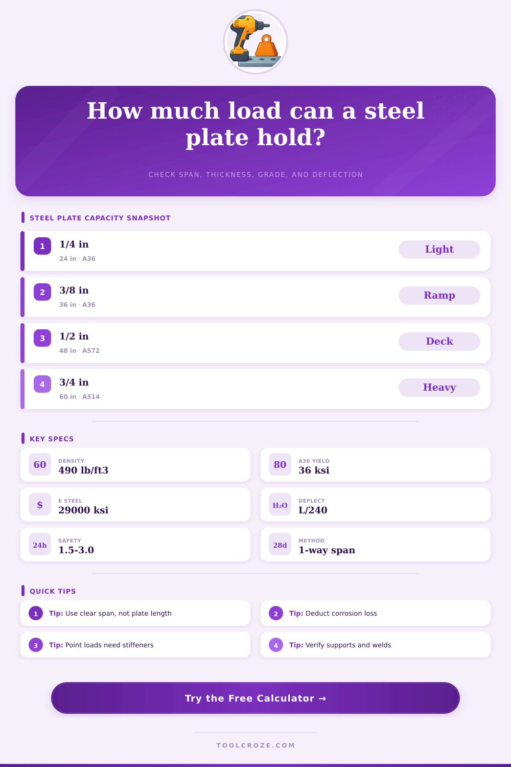
Estimate one-way bending capacity, deflection, self-weight, stress utilization, and practical safety margin for steel plates spanning between supports.
⚙Real Plate Presets
📏Plate And Load Inputs
🧱Selected Material / Spec Grid
📊Steel Plate Grade Reference
| Material | Typical yield | Modulus | Common use |
|---|---|---|---|
| ASTM A36 | 36 ksi / 250 MPa | 29,000 ksi | General base plates, covers, brackets |
| ASTM A572 Grade 50 | 50 ksi / 345 MPa | 29,000 ksi | Structural deck plates and frames |
| ASTM A588 Grade 50 | 50 ksi / 345 MPa | 29,000 ksi | Weathering structural plate |
| ASTM A514 | 100 ksi / 690 MPa | 29,000 ksi | High-strength ramps and heavy covers |
| 304 stainless | 30 ksi / 205 MPa | 28,000 ksi | Corrosion-resistant pans and floors |
| AR400 plate | 155 ksi / 1070 MPa | 29,000 ksi | Abrasion plate, not always structural-rated |
📐Support And Load Case Coefficients
| Case | Max moment | Deflection formula | Use when |
|---|---|---|---|
| Simple + uniform | wL²/8 | 5wL⁴/384EI | Plate bears on two opposite edges |
| Simple + center patch | PL/4 | PL³/48EI | Wheel or pad near midspan |
| Fixed + uniform | wL²/12 | wL⁴/384EI | Edges are welded or clamped rigidly |
| Fixed + center patch | PL/8 | PL³/192EI | Patch load with restrained rotation |
| Cantilever + uniform | wL²/2 | wL⁴/8EI | Shelf plate welded at one side |
| Cantilever + end patch | PL | PL³/3EI | Worst case tip load |
🔧Common Plate Thickness Reference
| Nominal plate | Decimal thickness | Weight per ft² | Typical check |
|---|---|---|---|
| 3/16 in | 0.188 in / 4.8 mm | 7.65 lb/ft² | Light covers, guards |
| 1/4 in | 0.250 in / 6.4 mm | 10.21 lb/ft² | Walk plates, small covers |
| 3/8 in | 0.375 in / 9.5 mm | 15.31 lb/ft² | Ramps, wheel pads |
| 1/2 in | 0.500 in / 12.7 mm | 20.42 lb/ft² | Trench plates, equipment bases |
| 3/4 in | 0.750 in / 19.1 mm | 30.63 lb/ft² | Road plates, heavy support |
| 1 in | 1.000 in / 25.4 mm | 40.83 lb/ft² | Heavy machine support |
🛠Practical Application Reference
| Application | Typical input | Key limit | Field note |
|---|---|---|---|
| Trench cover | 1/2 in A36, 36 in span | Bending and bearing | Provide full edge seating |
| Forklift crossing | 3/4 in A572, wheel patch | Patch bending | Check axle load per wheel |
| Mezzanine deck | 1/4 in A36, uniform load | Deflection | Use joist spacing as span |
| Dock ramp plate | 3/8 in A36, 30 in span | Impact allowance | Add ribs for repeated traffic |
| Machine base | 1 in A572, pad load | Bearing and vibration | Use grout or shims under pads |
ℹPlate Calculation Tips
There’s a steel plate in your hands and a muddy trench below you. And you know: A thing’s strength depend more on how it relates to the world around it than on the thing itself. How does this piece of steel respond to amount of force placed upon it? To the span? To gravity? Placement determines whether a half-inch plate buckle under a bicycle or holds a truck. So is the whole system.
Give the calculator above the load type, the geometry and let it do the tricky math for you. No more guessing if you’ve done it right or merely gotten away with it.
How to Choose the Right Steel Plate
The key dimension isn’t necessarily the whole length of the plate, but rather the clear span (distance) it’s attached to between supports. Frequently I’ve seen people confuse physical dimensions of a sheet of steel with its ability to hold weight. If you have a 12 foot long plate sitting on walls at both ends then that will behave quite different than one supported only in the middle. How much does this need to bend? To know that, we need to know what is holding the plate up and distance to the next support. Measuring from the edge of one support to the next give you the actual span, which influences all the other calculations in the tool.
Everything after that depends upon support conditions. A plate simply laid across two beams will deflect much more then one that is clamped or welded firmly at the edges. If it’s fixed then the moment is reduced dramatically as there’s no rotation allowed at the point of attachment. The worst-case scenario in terms of bending stress are a cantilever setup. This happens when you weld a shelf to only one wall. The calculator alters its coefficients depending off this choice. This is why a small change to how you mount your plate can make it one and a half or twice as strong without changing the steel itself.
For short spans, thickness of the materials is more important than the grade; for longer spans, the material grade are essential. In general construction applications, mild A36 steel is most common since it’s easy to bend (with consistent results) and easy to weld. If you want something much stronger, there are higher grades such as A514, but this material also comes with some challenges during welding which may compromise your weld if done incorrecty. Then stainless steel provides corrosion protection. However, the yield strength of stainless steel can be lower than carbon steel, which means you’ll require thicker gauge material to get equivalent stiffness. This table on the page explains different materials so you can select by durability requirements rather than simply following raw strength values.
Even when a temporary structure passes bending checks, its main weakness will be found through deflection. Technically speaking, a plate can hold weight of a forklift without breaking, yet if it droops significantly beneath the load, you’ll have a bump that jars the equipment and startles the driver. To keep the surface feeling solid underfoot, limit deflection to L/240 or stricter. In terms of mezzanines and walkways, this comfort factor is every bit as important as safety. You don’t want it to feel like walking on a trampoline; you want floor to feel rigid.
Uniform distributed weight is one mental model; patch loads are another. When we use a forklift wheel, all of that concentrated force goes onto a tiny contact area, generating very large stress locally on the metal. That’s why the tool estimates how far it spreads out (effective width) and then considers how much of that point load penetrates plate thickness. It avoids underestimating the local stress at the point underneath heaviest tires or jack stand. We commonly make the mistake of not accounting for concentration, which causes surprise failures in what appears to be a robust setup.
For corrosive environments (both outdoors and in harsher industrial applications), there’s also corrosion allowance. This is that little bit of extra thickness subtracted from the total as a safety factor against materials degrading over time. Even though your plate might be exposed for years, it’s still going to be safe. It is small, but it is important when you’re building something intended to last.
If the span becomes excessive, always put some sort of stiffener under point loads as thin plates can’t spreads concentrated forces very well on their own. There are safety factors built in to handle those unaccounted-for variables of the field conditions. For controlled environments, a factor of 1.5 does the trick, though you might want to increase that and add some cushion to your design with impact loading by vehicles or uneven settlement of the ground at 2.5 or even 3.0. It is better to use slightly thicker steel than to risk a sudden yield under unexpected dynamic forces.
In the end, figuring out what a plate can hold isn’t so much about learning equations as it’s learning about load paths. Weight is on the top surface and you’re directing it downward toward the support without exceeding strength of the material in between. That number tells you if your path is clear. Now that you’ve got your backside perched above that trench once more, you’ll find safety in knowing how to measure the span accurately, anchor the edges securely and appreciate the distinction between supporting weight vs. Keeping something steady. A plate is simply a means to connect two things, and its strength lies in how well you manage that connection.
You should of checked your math twice.