Sheet Metal Bend Calculator
Estimate bend allowance, bend deduction, K-factor layout, outside setback, springback cue, and flat pattern length from real sheet metal bend inputs.
⚙ Bend Presets
📏 Calculator Inputs
Calculation Breakdown
🔧 Material / Spec Grid
📊 Reference Tables
| Material | Minimum inside radius | Starting K-factor | Springback cue |
|---|---|---|---|
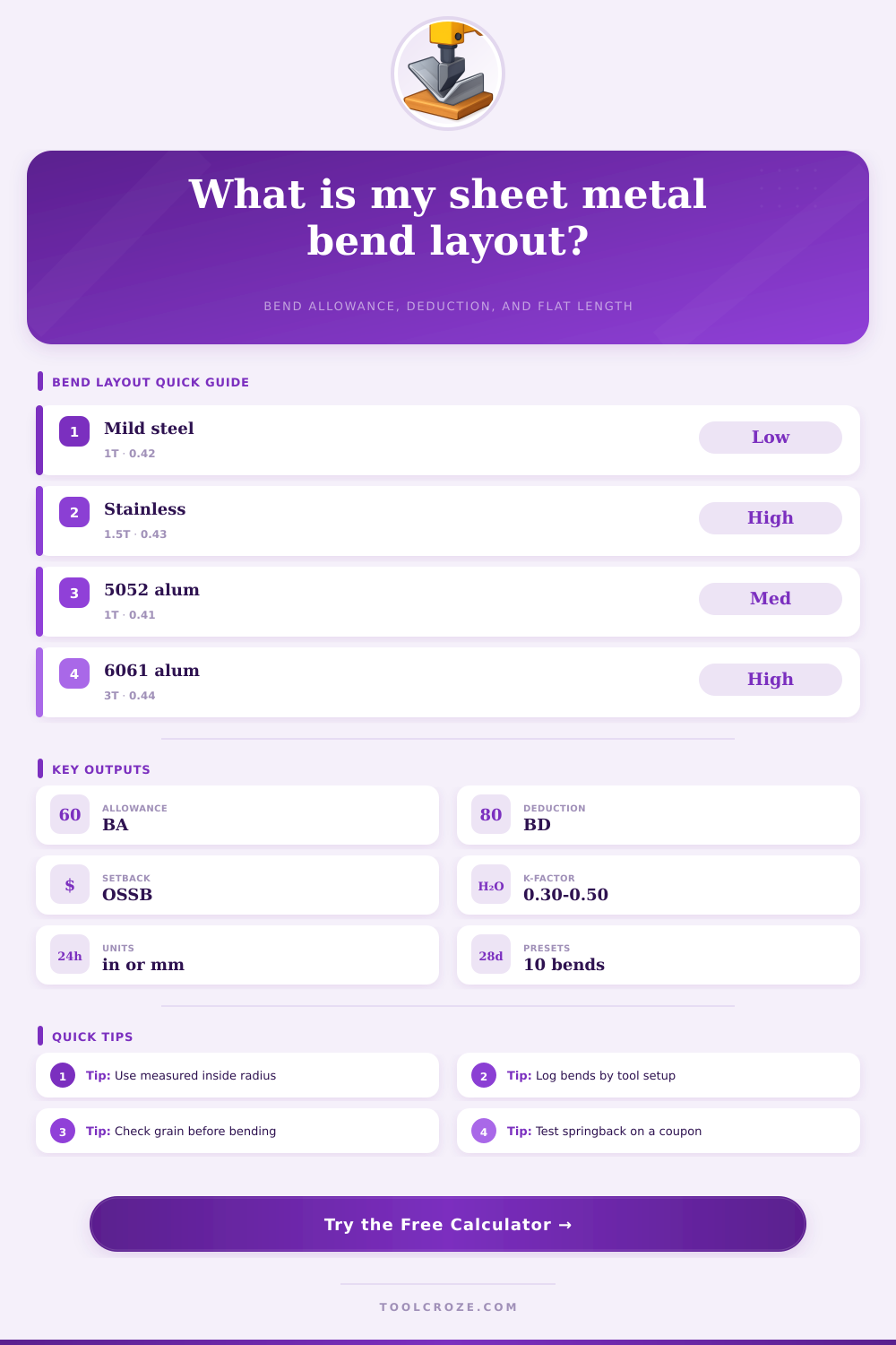
| Mild steel | 1.0T | 0.42 | Low to moderate; common press brake baseline |
| Cold rolled steel | 1.0T | 0.40 | Moderate; watch grain on tight bends |
| Galvanized steel | 1.0T | 0.42 | Low to moderate; coating can craze |
| 304 stainless steel | 1.5T | 0.43 | High; expect angle overbend trials |
| 5052-H32 aluminum | 1.0T | 0.41 | Moderate; good forming aluminum |
| 6061-T6 aluminum | 2.5T to 3T | 0.44 | High; tight bends may crack |
| Copper C110 | 0.5T to 1T | 0.38 | Low; soft material marks easily |
| Cartridge brass | 1.0T | 0.39 | Moderate; grain direction matters |
| Bend method | K-factor tendency | Radius control | Best calculation use |
|---|---|---|---|
| Air bend | Mid range, often 0.38 to 0.45 | Die opening and springback dominate | General flat pattern estimates |
| Bottom bend | Slightly lower after tooling contact | Punch and die seat more firmly | Repeatable shop setups |
| Coining | Lower to mid, but tonnage sensitive | Tooling forces a sharper inside shape | Tight bends after capacity check |
| Wipe bend | Lower to mid with clamp influence | Wipe die and flange length matter | Flanges, covers, and lips |
| Roll / large radius | Higher, often near 0.48 | Large arc shifts neutral axis outward | Curved panels and radius parts |
| Angle | Radians factor | Setback term | Typical part cue |
|---|---|---|---|
| 30° | 0.5236 | tan 15° | Pre-bends and shallow offsets |
| 45° | 0.7854 | tan 22.5° | Trim angles and guards |
| 60° | 1.0472 | tan 30° | Architectural returns |
| 90° | 1.5708 | tan 45° | Brackets, channels, enclosures |
| 120° | 2.0944 | tan 60° | Open frames and troughs |
| 135° | 2.3562 | tan 67.5° | Flashing and obtuse bends |
| Preset | Material and thickness | Radius and angle | Layout note |
|---|---|---|---|
| 16 ga steel bracket | Mild steel, 0.0598 in | 0.063 in, 90° | General shop bracket blank |
| 22 ga duct flange | Galvanized, 0.0299 in | 0.032 in, 90° | Light flange with small trim allowance |
| 304 stainless panel | Stainless, 0.0478 in | 0.075 in, 90° | Springback coupon strongly advised |
| 5052 enclosure side | 5052-H32, 0.080 in | 0.080 in, 90° | Good aluminum enclosure baseline |
| 6061 support angle | 6061-T6, 0.125 in | 0.375 in, 90° | Generous radius to reduce cracking |
| Metric U-channel | Mild steel, 3 mm | 3 mm, 90° | Two-bend channel layout |
💡 Shop Tips
When you’re just learning to bend a simple bracket, and before you start factoring in the flat pattern, the math seem hard. You measure your flanges on the completed drawing. Add those numbers together. Cut that length off a piece of stock and take it over to press brake. Watch as the press brake eats several millimeters of material. Your part’s too short, your flanges aren’t squared, and you have a pile of now-useless, costly scrap staring at you asking what happened.
That’s the difference between pros and hobbyists… It’s not your tools or your vision, it’s your lack of knowing how metal will behave when tensed. The calculator above handles the heavy lifting once you input your material specs. It saves you from the guesswork that usualy leads to ruined blanks.
Why Sheet Metal Bending Is Hard for Beginners
Sheet metal isn’t flexible like a hinge. Instead, it compresses on one side while stretching on the other. A neutral axis exist halfway between two, remaining exactly the same length at all times. As a fabricator, you must locate that invisible line and measure to match. Unfortunatley, most people simply use outside measurements because that’s what they see. The real deal require considering arc length within that neutral layer, which include the blank. Bend allowance cannot be changed here.
In essence, you’re figuring out the circumferential measurement of a wedge-shaped slice of pizza. Only the diameter of the circle shift based off thickness and alloy type. Fail to do so, however, and each 90-degree bend will cost you approximately 15 percent of the flange length you was hoping for. Sounds trivial? It is not trivial when you consider having to do it on a single component six times over.
The K-factor (ratio of depth of the neutral axis to the overall thickness) is dictated by the type of material used, and it defines the position of the neutral axis. For mild steels, this tends toward about a K-factor of 0.42; harder alloys such as hardened aluminum or high-strength stainless tend to be less stretchy, pushing the K-factor higher. Fortunately, the tool include reference tables that plot out this tendency for you, so you won’t have to remember how any given alloy will behave.
A nasty characteristic of stainless steel in particular is its tendency to bounce back after being released from pressure: If you are bending something at 90 degrees, then lift the pressure, it may well open up to 88 degrees when the pressure are removed. Overbending a bit compensate for that spring-back tendency. Having an idea of where your material falls on the high-springback-low-springback spectrum is half the battle.
The other silent killer on shop floors everywhere is called springback. You deform this material against its will, but eventually it want to get back into its original form. Harder temper materials (like 6061-T6 aluminum) and tighter radii makes this effect worse. Based off the method and alloy selection, the calculator provide a hint of springback as a cue that’s more of a practical rule of thumb than a rigid law. It warns you where trouble might be. When the cue flags high risk, you know to test a coupon first or make incremental adjustments to your angle instead of blindly trusting the theoretical math. Testing is cheap; reworking production parts isn’t.
For one thing, there’s the setup of the tools and grain direction. With air bending, you can adjust the die opening to somewhat control the radius. However, this create variability that is removed by coin bending or bottom bending the metal. This changes the stress distribution inside the part, which moves your K-factor as well based on how deep the punch goes vs. Merely pressing down on it. This is where the calculation start to turn from an abstract equation into something that will work for you given your specific shop condition.
In summary, when we talk about sheet metal, you cannot cheat the physics of bending. If you treat the flat pattern as just the sum of the parts you see instead of the calculated result, you are fighting against your own material. Use a coupon, check the K-factor against real life, and let the math take over from there. Your flanges will be square, your brackets will fit and that pesky missing length wouldn’t go anywhere but right back where it was supposed to be all along.