Shackle Angle Calculator
Estimate shackle capacity from rated WLL, side load angle, sling angle, bow or pin loading, number of shackles, load sharing, derate factor, and planning margin.
⚙Real Shackle Angle Presets
📏Rigging Inputs
🧱Shackle Type / Spec Grid
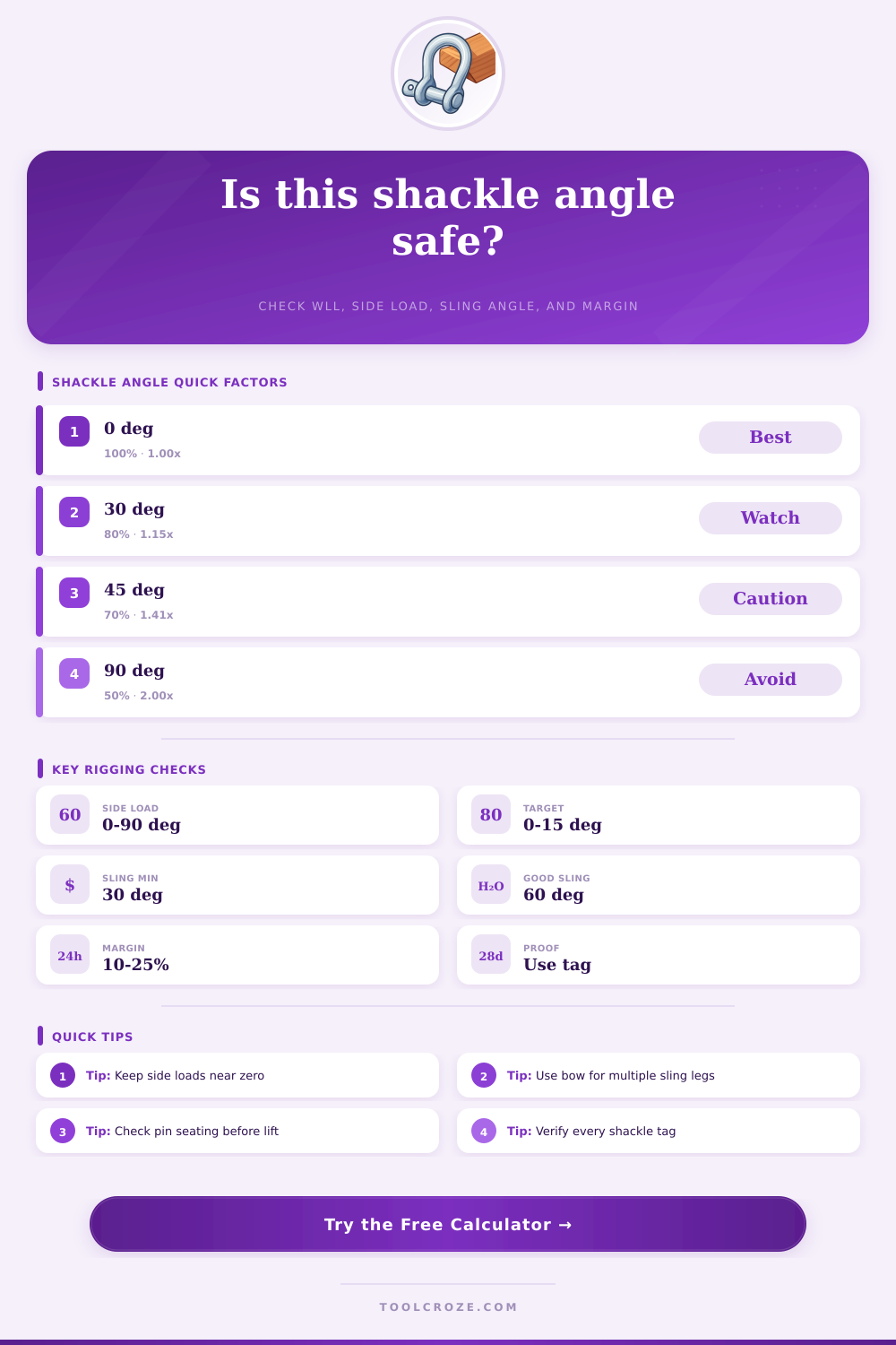
📊Side Load Angle Reference
| Side load angle | Planning factor | Capacity effect | Rigging note |
|---|---|---|---|
| 0° in-line | 1.00 | Full entered WLL before other factors | Preferred loading path through pin and bow centerline |
| 15° side load | 0.90 | Small planning reduction | Correct geometry if possible before lifting |
| 30° side load | 0.80 | Noticeable WLL loss | Check manufacturer side-load chart |
| 45° side load | 0.70 | Common published derate point | Use only when shackle is approved for side loading |
| 90° side load | 0.50 | Severe WLL reduction | Avoid unless permitted by the exact shackle chart |
📐Sling Angle Tension Reference
| Sling angle from horizontal | Sine factor | Tension multiplier | Planning note |
|---|---|---|---|
| 90° | 1.000 | 1.00 times vertical share | Vertical leg, lowest shackle tension |
| 75° | 0.966 | 1.04 times vertical share | Excellent bridle geometry |
| 60° | 0.866 | 1.15 times vertical share | Common target for routine lifts |
| 45° | 0.707 | 1.41 times vertical share | Verify all hardware and load control |
| 30° | 0.500 | 2.00 times vertical share | Generally avoid without qualified lift planning |
🔗Bow / Pin Loading Reference
| Loading condition | Calculator factor | Best use | Watch point |
|---|---|---|---|
| In-line pin or bow loading | 1.00 | Straight pull through shackle centerline | Pin must be fully engaged and seated |
| Wide synthetic sling in bow | 0.95 | Soft bearing with broad contact | Confirm sling fits without bunching |
| Screw pin temporary condition | 0.90 | Short picks with monitored pin position | Avoid sling rotation that can open the pin |
| Two sling legs bearing in bow | 0.85 | Bridle legs seated evenly in anchor bow | Included angle can spread the bow |
| Point load or poor pin seating | 0.75 | Conservative estimate only | Correct the connection before lifting |
🛠Shackle Type Selection Reference
| Type | Typical role | Angle suitability | Spec check |
|---|---|---|---|
| Anchor bow shackle | Slings, hooks, multiple rigging points | Best general shape for bridle connections | Use marked WLL and manufacturer side-load data |
| Chain D shackle | Single in-line chain or eye connection | Poor for multi-direction loading | Keep pull centered and straight |
| Screw pin anchor | Temporary lifts and frequent changes | Acceptable only when pin cannot loosen | Pin shoulder fully seated, threads engaged |
| Bolt type anchor | Longer lifts, vibration, repeated service | Preferred for sustained rigging | Bolt, nut, and cotter installed correctly |
| Wide body sling shackle | Soft sling support and sling efficiency | Good when sling width is matched | Verify radius and sling contact area |
💡Rigging Calculation Tips
The decisions you make in rigging work can compound quick. For example, the capacity of a shackle is reduced dramatic if the angle at which a load is applied to the shackle is not 0 degrees. Many people knows that a straight pull is the best way to use a shackle; however, the geometry of many lift makes it impossible to pull a load directly through a shackle.
Because a straight pull is impossible, there is always a gap between the ideal rigging solution and the actual rigging solution that must be used. This gap is where risk exist for a lift. A primary cause of risk is side loading of a shackle.
How Angles, Sling Tension and Load Sharing Affect Shackles
Side loading means that the load is applied to the shackle at an angle such that the load does not pass through the shackle pin in a straight lines. Manufacturers publish derate curves that illustrate the impact of side loading on the working load limit of shackles. Even a small degree of side loading can reduce the working load limit of the shackle.
For example, a fifteen-degree angle can reduce the capacity of the shackle by ten percents. A calculator can be used to calculate the impact of a particular angle on a shackle. Using a calculator eliminates the need for the rigging specialist to remember derate curves for shackles under a load.
Sling angles presents a separate problem from side loading, yet the sling angles have an impact on the capacity of the rigging. The smaller the sling angle from the horizontal, the higher the tension in each sling leg. For example, at a sixty-degree sling angle each sling leg must exert a force equal to the vertical load.
At a thirty-degree sling angle each sling leg must exert a force equal to twice the vertical loads. It is this increase in sling tension that can lead to overloading shackles. The tension calculation in the calculator takes into account this increase in tension so that rigging specialist have an accurate idea of the load on shackles in a lift.
The condition of the shackle bow and shackle pin can create yet another layer of complexity in rigging work. Shackles are rated for straight pulls through the shackle pin. However, it is common for two or three sling legs to apply a load to the shackle bow rather than the shackle pin.
Additionally, the load on a wide synthetic sling can spread across the shackle bow. Screw pin shackles pose a unique problem in that the shackle pin can rotate under a load. If the shackle pin rotates, the pin can back out of the shackle.
Load sharing factor can be programmed into the calculator so that the rigging specialist can apply a realistic factor to shackles rather than assuming there published rating is valid in all situations. Load sharing amongst shackles is rarely perfect. Shackles on the corners of a four-point lift may not share the load equally.
One corner may have more load than the other three corners. Using the load share option in the calculator allows the rigging specialist to model this load imbalance. It is always better to model this situation than to hope for perfection in the geometry of a lift.
Using a conservative factor for load sharing among shackles provides a safety margin that can help prevent surprises during a lift. The derate factors and planning margins creates the last layer of protection in the rigging process. There are always variables in the rigging process that are not accounted for in any planning.
Applying an additional derate and planning margin allows for these unaccounted for variables. Building room in the rigging plan for unknown variables prevents the rigging specialist from guessing at the rigging plan. The calculator incorporates these derate factors and planning margins to arrive at a single adjusted capacity for shackles.
This single number makes it easier for the rigging specialist to determine if shackles are adequate for a job or if the hardware must be changed. Common mistake in rigging work involve certain habitual behaviors. One habit is to ignore the impact of angles on shackles; shackles are rated for straight pulls and every angle reduces their working load limit.
Another habit is to forget about sling tension with flat sling angles. Lastly, many rigging specialists will select shackle hardware to handle the largest single load but often forget that the hardware must also handle the side load on the shackle. Before entering a load into a calculator, one should review the reference tables that show the impact of side load, sling angle, and shackle bow on shackles.
The multipliers dont need to be memorized, but reviewing the reference tables and the multipliers helps to increase the understanding of the impact of each of these variable. For example, a fifteen-degree side load is manageable with the proper hardware; however, a ninety-degree side load with any hardware is rarely safe. The goal in rigging work is to become familiar with the capabilities of the hardware that will be used in a lift.
If the adjusted capacity for shackles is higher than the calculated tension the rigging specialist has for the load being lifted there is room for small surprises during the lift. However, if the adjusted capacity is not higher than the calculated tension the tool will indicate which aspect of the rigging plan is creating the shortfall in capacity. Knowing the cause of the shortfall allows the rigging specialist to make a decision about whether to change the angle, add another shackle, or change hardware.
The principles of rigging work are applicable to both a single machine and to multi-point lifts. The physics of rigging do not change with the size of the lift. However, the consequence of getting the rigging plan wrong change with the size of the object that is to be lifted.
It is always a good idea to use the rigging calculator to determine if the lift will go smoothly.