Rigging Bridle Calculator
Estimate bridle leg lengths, sling angle, maximum leg tension, CG offset effect, trim correction, and hardware utilization for two, three, and four-leg picks.
1Bridle presets
2Calculator inputs
3Bridle results
4Bridle hardware/spec grid
5Formula breakdown
| Calculation | Formula | What it checks | Notes |
|---|---|---|---|
| Leg length | sqrt(height^2 + horizontal distance^2) | Each bridle leg | Hook is assumed over the entered CG offset |
| Sling angle | atan(height / horizontal distance) | Angle from horizontal | Lower angles multiply leg tension |
| Leg tension | vertical share / sin(angle) | Per-leg tension | Dynamic factor is applied to the load |
| Required WLL | max tension x (1 + margin) / derate | Minimum sling tag | Compare with the weakest rated component |
6Reference tables
| Sling angle | Angle factor | Bridle behavior | Planning use |
|---|---|---|---|
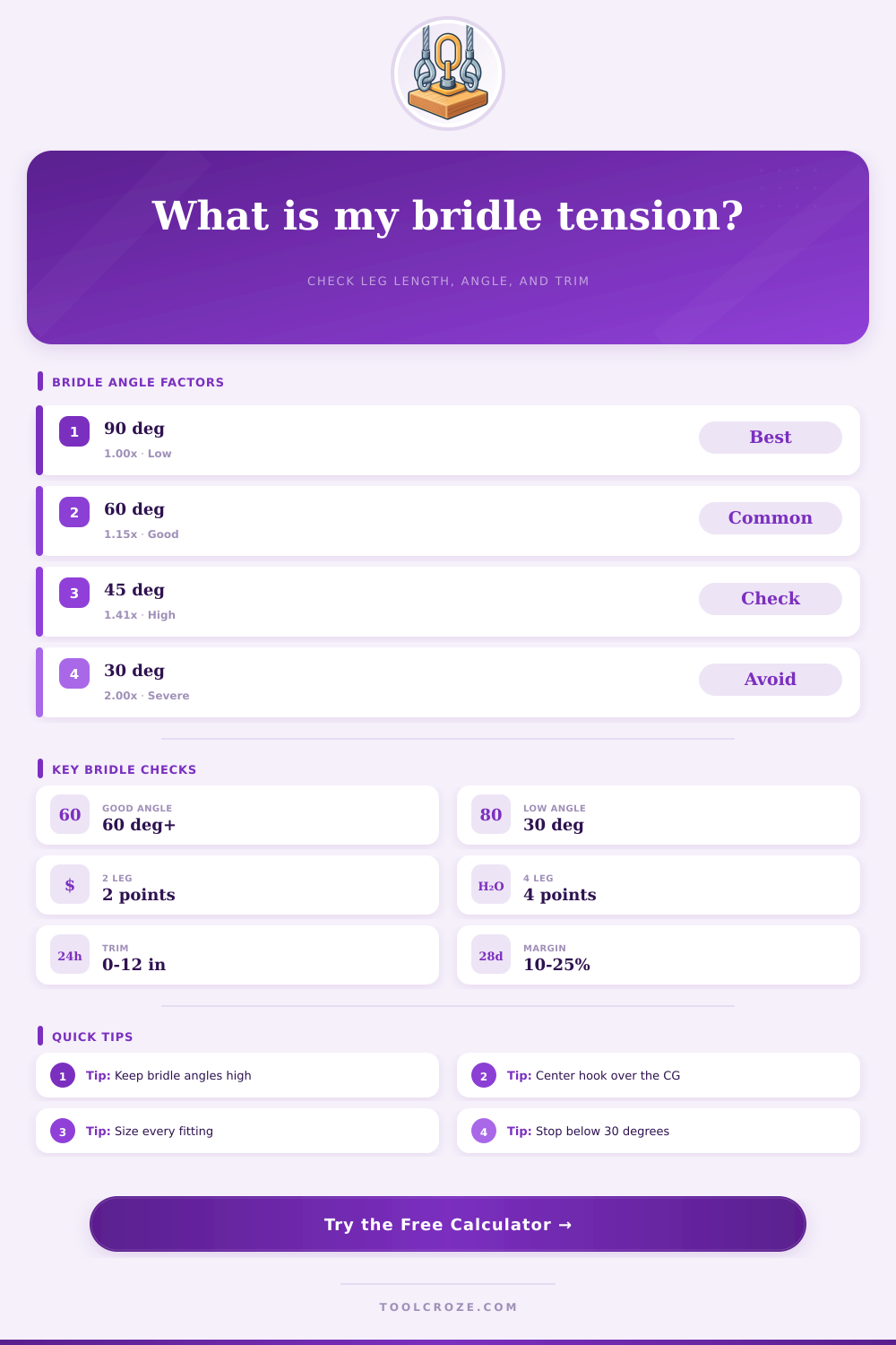
| 90 deg | 1.00x | Vertical legs, lowest tension | Best if geometry allows |
| 60 deg | 1.15x | Common field target | Good starting check |
| 45 deg | 1.41x | Tension is climbing fast | Verify every fitting |
| 30 deg | 2.00x | Severe bridle loading | Avoid without qualified review |
| Bridle layout | Best use | Load share assumption | Main caution |
|---|---|---|---|
| 2-leg inline | Beams and long frames | CG split along one span | Side stability may need control |
| 3-leg triangle | Tanks and odd shapes | Estimated by leg position | One leg may dominate quickly |
| 4-leg rectangle | Skids and machines | Bilinear CG split | Rigid loads may not share equally |
| Adjustable chain | Uneven pick points | Trim can level the load | Shortened leg can gain load |
| Trim amount | Typical use | Estimated effect | Field note |
|---|---|---|---|
| 0 in | Balanced load | No correction | Confirm CG before lifting |
| 1-2 in | Small CG offset | Fine leveling | Common chain sling adjustment |
| 3-6 in | Visible nose tilt | Moderate correction | Recheck leg tension |
| 6+ in | Large offset | Strong correction | Use a qualified rigging plan |
| Hardware item | Check against | Calculator output | Practical limit |
|---|---|---|---|
| Master link | Total lifted load | Factored load | Must fit hook and bridle legs |
| Shackle or hook | Highest leg tension | Max leg tension | Avoid side and tip loading |
| Sling leg | Tagged WLL | Required leg WLL | Use the weakest leg rating |
| Adjuster | Shortened leg load | Trim group tension | Lock before raising load |
7Tips and safety note
A bridle is a rigging tool that is used when the hook cannot sit direct above each pick point of the load. The bridle tool use multiple sling legs to attach the hook to the load. The geometry of these sling legs change the load that each sling leg must bear.
If the height of the hook changes or if the spacing between the pick points change, the tension that each sling leg must bear will change. Because each sling leg and the hardware that connects the sling legs to the load will experience an increased tension, riggers often calculate the tension that each sling leg will experience before beginning the lift. The calculator output mathematical answers to the questions based off the information you enter.
How to Use a Sling Leg Tension Calculator
The information that you must enter includes the weight of the load, the number of sling legs, the spacing between the pick points, the height of the hook, and the loads center of gravity offset. Based upon this information, the calculator will provide the maximum tension for any single sling leg, the shallowest angle of the sling legs, the length of each sling leg, and the percentage of the hardware that will be utilized during the lift. The utilization percentage allow the rigger to determine if the hardware will remain within the working load limits of the hardware.
The angle of each sling leg is a variable to consider in the lift. If the angle of each sling leg is 90 degrees, the tension within each sling leg is equal to the load that each sling leg is assigned. However, if the angle of each sling leg decreases to 60 degrees, the tension within each sling leg will increase 15%.
If the angle of each sling leg decreases to 45 degrees, the tension within each sling leg will increase 40%. If the angle of each sling leg decreases to 30 degrees, the tension within each sling leg will double. Due to the increased tension within each sling leg as the angle of the sling legs decrease, riggers will typically avoid using sling leg angles below 30 degrees.
By reviewing the angle of each sling leg that the software calculates, the riggers can decide if the height of the hook should be increased or if the pick points should be changed. The center of gravity of the load will impact how much each sling leg must bear. If the hook is not centered over the center of gravity of the load, one or more of the sling legs will have to bear more of the load than the other sling legs.
The offset of the center of gravity can be entered into the calculator to reflect how each sling leg will share the load. By entering the offset of the center of gravity of the load, the riggers will know that the front sling leg may have to bear more of the load than the other sling legs. By calculating the tension that each sling leg will experience with a load offset, the riggers will avoid the mistake of thinking that the load will be equally shared among each sling leg.
Trim adjustments to the sling legs can be used to level the load. The length of one or two of the sling legs can be shortened by a few inches to make the load level. The calculator will show the vertical effect of the trim adjustment to each of the sling legs, as well as the resulting tilt angle of the load.
If each of the sling legs is trimmed, the shortened sling legs will have to bear more of the load. The resulting tilt angle will allow the riggers to determine if the tension of each of the sling legs will still be within the limits of the safe tension limits of each sling leg. It is necessary to check the hardware that will be used to ensure the safety of the load.
The master link should be able to handle the full factored load of the load that will be lifted. Each of the individual shackles and hooks should be able to handle the highest tension of any single sling leg. By entering these specifications into the calculator, the software will calculate the percentage of each unit of hardware that will be utilized.
If the percentage is above 85%, the riggers should select a different piece of hardware. These reference tables will allow the riggers to decide if using a taller bridle is the best alternative to using a sling leg angle that is lower than the angle that the software calculates. The accuracy of the sling leg tension calculator is based upon the accuracy of the measurements that are entered into the software.
If the height of the hook is estimated from the ground, a two-foot error will change the tension of each sling leg by several percent. The accuracy of the distance between the pick points will make the tension calculations more accurate, but it is difficult to accurately measure the location of the center of gravity of the load. The accuracy of the measurements will have a direct impact upon the accuracy of the results that are provided to the rig team.
Many mistakes are made due to incorrect assumptions made by the riggers. For instance, one incorrect assumption is that each sling leg will have an equal share of the total weight of the load. If the center of gravity of the load is not accounted for in the calculations, the tension of the shortest sling leg will be underestimated.
Another common mistake is to ignore the dynamic factor. If the riggers do not account for the dynamic factor, the tension in each sling leg will be underestimated. Instead of calculating the sling leg angle and length of each sling leg, the riggers should decide on the angle of each sling leg first, then calculate the length of each sling leg to ensure that each sling leg has the same angle.
Depending upon the type of load that is to be lifted, there are various types of rigging setups that should be used. For instance, two-leg in-line bridles are used for long beams and for loads that are managed by the tag lines. Three-leg triangle bridle setups are used for round tanks, but one of the three sling legs will carry more of the load than the other two if the center of gravity of the load begins to drift towards one of the corners of the tank.
Four-leg rectangular bridles are often used for moving skids and heavy machines, but the slings may not share the load equally due to the stretch of each sling. Finally, adjustable chain slings allow for trim adjustments, but the tension on the shortened chain sling must be checked. The sling leg tension calculator is a tool that can assist the rig team in making decisions.
For instance, the calculator can be used to compare the tension of a bridle that has a sling leg angle of 60 degrees to one that has a sling leg angle of 45 degrees. The calculator can also be used to determine the effect that trim adjustments will have upon the tension of each sling leg. Furthermore, the calculator can be used to determine if the tension of the master link will be sufficient for the task.
By using the calculator, the riggers ensure that there is a safety margin for the rigging and the sling legs so that any error in measurement or movement of the load will not pose a problem for the riggers. While the sling leg tension calculator will assist in making the best decision regarding the rigging of the load, it should never be used in place of a qualified member of the rigging team. The calculator is a tool to assist the rig team with the planning of the lift and with making decisions about the rigging of the load.
Such decisions may involve comparing the tension of a 60 degree bridle versus a 45 degree bridle. The calculator will assist in confirming that the master link will be sufficient to handle the load. By using a sling leg tension calculator, the rig team ensures that there is a margin for error in the rigging of the load.