Rigging Angle Calculator
Estimate sling angle, included angle, hook height, angle factor, tension per leg, working load limit margin, and the effect of unequal leg sharing.
⚙Real Rigging Angle Presets
📏Rigging Inputs
📊Angle / Tension / Spec Grid
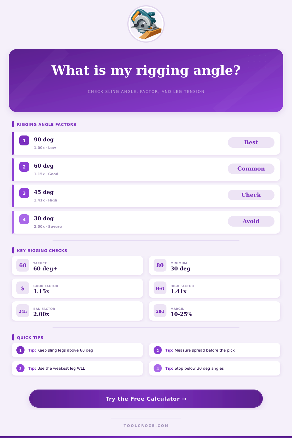
📐Sling Angle Factor Reference
| Sling angle from horizontal | Included angle between two legs | Angle factor | Rigging note |
|---|---|---|---|
| 90° | 0° | 1.00 times vertical share | Vertical leg, lowest tension for the same load |
| 75° | 30° | 1.04 times vertical share | Excellent bridle geometry with small tension increase |
| 60° | 60° | 1.15 times vertical share | Common target angle for routine two-leg lifts |
| 45° | 90° | 1.41 times vertical share | High enough to require careful WLL verification |
| 30° | 120° | 2.00 times vertical share | Generally avoid without a qualified lift plan |
📏Geometry Reference
| Known values | Formula | Use case | Watch point |
|---|---|---|---|
| Sling length and spread | Angle = acos(spread / length) | Fast check when the sling is already selected | Spread must be per leg, not total width |
| Hook height and spread | Angle = atan(height / spread) | Useful for low headroom planning | Height is vertical rise from load point to hook |
| Included angle | Sling angle = (180° - included) / 2 | Common bridle angle chart conversion | Only applies to matching opposite legs |
| Sling angle and load | Tension = load / legs / sin(angle) | Direct tension per leg estimate | Unequal loading can make fewer legs effective |
🔗Sling Type Planning Reference
| Sling or connection | Typical angle use | Spec check | Field note |
|---|---|---|---|
| Grade 100 chain sling | Good for bridle legs above 45° | Use rated WLL for the exact angle and hitch | Inspect hooks, latches, chain wear, and heat marks |
| Wire rope sling | Common for heavier multi-leg rigging | Check eye, fitting, and D/d reductions | Avoid kinks, broken wires, crushing, and sharp bends |
| Synthetic round sling | Useful where load surface protection matters | Match tag color, capacity, hitch, and angle | Protect from edges, heat, chemicals, and abrasion |
| Synthetic web sling | Stable bearing on broad contact areas | Use the tag for vertical, choker, or basket hitch | Do not use if cuts, knots, burns, or tears are present |
| Multi-leg bridle assembly | Designed for controlled multi-point lifts | Use assembly tag, not just single-leg ratings | Leg length mismatch can overload one or two legs |
🛠Load Share Reference
| Leg setup | Calculator assumption | When to use it | Result effect |
|---|---|---|---|
| Balanced two-leg bridle | 100% effective legs | Equal leg length and centered load | Lowest calculated tension per leg |
| Minor rigging imbalance | 87.5% effective legs | Small geometry or center of gravity uncertainty | Adds a moderate tension reserve |
| Conservative field check | 75% effective legs | Normal planning when exact share is unknown | Raises required WLL per leg |
| Four legs, three carrying | 67% effective legs | Rigid loads or uneven leg tension | Prevents crediting all four legs equally |
| Major imbalance | 50% effective legs | Uncertain center of gravity or poor geometry | Requires engineering or lift director review |
💡Rigging Angle Tips
In rigging a lift, an understanding of geometry help people understand the tension that each of the legs of the slings will have to carry. The angle between the hook and where the slings connect to the load will determine the tension in each of those slings. Additionally, the more flat the angle between the legs of the slings, the more tension each of those slings will have to endure.
Thus, before attaching any shackle hardware to the load, it is important to measure the dimension of the lift. The calculator allow for the entry of the weight of the load, the number of leg of the slings, the length of each of the slings, the height of the hook above the pick points of the slings, and the included angle between the slings. These measurements is often the easiest to take on the jobsite.
Check Sling Tension with a Lift Calculator
While such a calculator cannot replace the lift plan, the calculator will allow a rigger to have an immediate sense of whether or not the calculated values of the lift are safe to use on the load. The angle factor are used to calculate the tension that each of the legs of the slings will have to endure. For instance, if the angle of each of the slings to the load is 90 degrees, each of the slings will have to bear one share of the total weight of the load.
Decreasing that angle to 60 degrees will increase the angle factor to 1.15, indicating that each sling will have to carry 15% of the loads weight beyond the loads share divided equally between each sling leg. Thus, using the calculator allow for the angle factor to be determined without having to perform mental math calculations. The included angle calculations assumes symmetry in the load that is to be lifted.
In many instances, the load will not be symmetrical due to the position of the loads center of gravity, or due to the shortening of one of the slings relative to the others. The load share settings allow for each of the sling legs to be weighted differently; for example, if each leg is only 75% of the effective strength of a sling, the load share setting can be adjusted to reflect this. In these cases where there are fewer effective legs, the required working load limit for each sling will increase.
Furthermore, selecting an increased load share is a conservative approach in lift planning. While the angle calculations are independent of the types of slings that are to be used in the lifting operation, the choice of sling types does impact the decision of which slings to select. For instance, chain slings can better tolerate heat and abrasion than synthetic slings, but they are heavier and may leave marks upon contact with finished surfaces.
Synthetic round slings will not mark painted or machined surfaces, but the slings must be protected from any sharp edge that may cut the synthetic jacket of the sling. Thus, the user can select the sling family on the calculator to ensure that the derating and the margin settings is applied to the correct sling materials. The reference tables for sling angles and included angles allow those using the calculator to verify the calculations without relying upon the calculator; these tables is useful for those who wish to perform a rough estimation of the parameter of the lift.
For example, using a sling angle and included angle of 60 degrees is common for two-leg bridle slings. For any sling angle below 30 degrees, the angle factor doubles; thus, most lifting crews will not use slings with angle this low unless the engineer on the job has reviewed and approved of such use. In addition to the factor that can be entered into the calculator, the hook height above the pick points is a value that must be entered into the calculator.
In some instances, there is a lack of headroom on the jobsite to allow the hook to rise to the height required to create the angles needed for the slings to have a reasonable amount of tension. By entering the hook height, the calculator will reveal the derived height that the hook must rise to, allowing the rigger and the supervisor to both understand what constraints exist. The margin and derate settings are used to account for the difference between the calculator and the actual job site.
For instance, the planning margin is often between 10 and 15% to account for human error. Additionally, the derate can be used to account for the use of the slings in heavy use prior to being used for lifting the load. Thus, the margin and derate will result in a value for the required working load limit for each of the slings.
While the calculator provides an understanding of the tension that each sling will have to endure, there are some common mistake that can occur in setting up the lifts. For instance, the spread of the slings must be measured for each of the individual legs of the slings; the spread should not be the total distance between the pick points of each leg. Additionally, the length of each sling must be measured from the master link and the hook of the sling to the load to be lifted; the length should not be measured from end of one eye of the sling to the end of the other eye.
Another of the common mistakes is in the assumption that each of the legs of a bridle lift is equally effective; in rigid loads, or lifts where one of the slings is of a different length than the others, each of the legs will not evenly share the weight of the load. Thus, the load share options on the calculator will allow the lift supervisor to account for this. By utilizing the load share options for the legs of the slings, the required working load limit will be higher for each of the slings.
Thus, this option allow riggers to avoid performing unsafe lifts. One of the benefits of using the sling lift calculator is that problems with the proposed lift can be found while the load is still on the ground. For instance, if the loadings of the slings is determined to be beyond the working load limit of the slings, there is time to either purchase new slings or to change the hitch of the sling prior to beginning to lift the load.
For the same reasons that a flatter angle increases the tension of the slings, a flat angle will likewise reduce the clearance that the load will have. A flatter angle means that the hook will be lower to the load than if the angle of the slings were higher. Thus, if too low a hook height is entered into the calculator, the slings may hook into the load, but may also hit another load or the load itself.
Thus, the derived hook height will allow the supervisor or the rigger to understand these issues. Overall, the sling lift calculator will transform the measured distance of the slings into the usable load values. The calculator cannot replace inspection of each of the slings, and does not account for loads created by wind or shock loading to the load.
However, the calculator will provide the rigger and the supervisor with an understanding of whether or not the slings will remain within their working load limits. Thus, the calculator allows lift crews to focus upon their experience and their knowledge of the load, rather than upon the calculations.