Rebar Spacing Calculator
Calculate a two-way rebar layout from finished concrete dimensions, cover, spacing, stock bar length, lap splices, layers, trim allowance, and waste.
⚙Topic-Specific Presets
Load a common concrete layout, then adjust dimensions and spacing to match your drawing.
📏Layout Inputs
Rebar Layout Results
🔧Material and Spec Grid
📊Rebar Size Reference
| US size | Metric equivalent | Diameter | Area | Nominal weight |
|---|---|---|---|---|
| #3 | 10M | 0.375 in / 9.5 mm | 0.11 in² / 71 mm² | 0.376 lb/ft / 0.560 kg/m |
| #4 | 13M | 0.500 in / 12.7 mm | 0.20 in² / 129 mm² | 0.668 lb/ft / 0.994 kg/m |
| #5 | 16M | 0.625 in / 15.9 mm | 0.31 in² / 200 mm² | 1.043 lb/ft / 1.552 kg/m |
| #6 | 19M | 0.750 in / 19.1 mm | 0.44 in² / 284 mm² | 1.502 lb/ft / 2.235 kg/m |
| #7 | 22M | 0.875 in / 22.2 mm | 0.60 in² / 387 mm² | 2.044 lb/ft / 3.042 kg/m |
| #8 | 25M | 1.000 in / 25.4 mm | 0.79 in² / 510 mm² | 2.670 lb/ft / 3.973 kg/m |
📐Spacing and Cover Reference
| Concrete member | Typical bar | Common spacing | Typical cover | Calculator check |
|---|---|---|---|---|
| Patio or sidewalk slab | #3 to #4 | 16 to 24 in each way | 1.5 to 2 in | 24 in maximum |
| Driveway or garage slab | #4 to #5 | 12 to 18 in each way | 2 in typical | 18 in maximum |
| Strip footing | #4 to #6 | 8 to 16 in transverse | 3 in earth cast | 12 in maximum |
| Wall or stem wall face | #4 to #6 | 12 to 18 in vertical/horizontal | 1.5 to 2 in | 18 in maximum |
| Mat or heavy equipment slab | #5 to #8 | 6 to 12 in each way | 2 to 3 in | 12 in maximum |
🔗Lap and Stock Length Reference
| Bar size | 40 diameters | 48 diameters | Common stock | Use in calculator |
|---|---|---|---|---|
| #3 | 15 in | 18 in | 20 ft or 40 ft | 18 to 24 in lap |
| #4 | 20 in | 24 in | 20 ft or 40 ft | 24 to 30 in lap |
| #5 | 25 in | 30 in | 20 ft or 40 ft | 30 to 36 in lap |
| #6 | 30 in | 36 in | 20 ft or 40 ft | 36 to 48 in lap |
| #8 | 40 in | 48 in | 20 ft, 40 ft, 60 ft | 48 in or engineered |
🏗Project Layout Reference
| Project preset | Typical dimensions | Bar layout | Cover basis | Watch item |
|---|---|---|---|---|
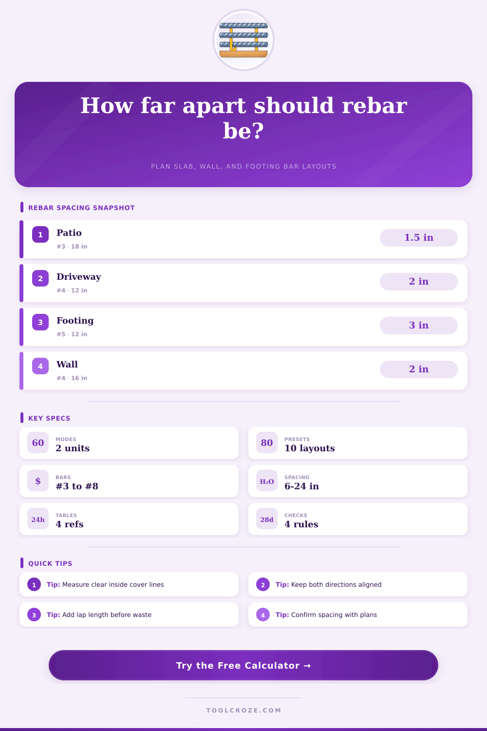
| 4 in patio slab | 12 ft × 16 ft | #3 at 18 in each way | 1.5 in edge | Chair height and edge cover |
| Driveway panel | 12 ft × 20 ft | #4 at 12 in each way | 2 in edge | Joint locations and saw cuts |
| Strip footing | 30 ft × 2 ft | #5 at 12 in transverse | 3 in earth cast | Hooks and corner laps |
| Stem wall grid | 28 ft × 8 ft | #4 at 16 in each way | 2 in face | Vertical dowel alignment |
| Mat foundation | 24 ft × 24 ft | #6 at 8 in each way | 3 in bottom | Two layers and bar supports |
💡Calculator Tips
To most of us, a concrete slab is just a boring expanse of gray. We don’t think of the metal bones that connect them all. Those form the structure that keeps driveways from splitting apart in winters chill. Rebar placement is far more important then texture choice. Getting this part correct ensures longevity (decades) instead of failure (early).
Once you input your size into the tool above, the math happen for you; no need to worry about unit conversion or other factors. It’s really all about some basic geometry and structure requirements. Certain areas of space must be covered. Bars should be placed far enough apart to allow for easy pouring, but close enough together to support tension. You need to know what each measurement signify.
How to Use Rebar Correctly
Setting the cover too high or low has an effect on both structural depth and whether or not you see any rebar. The cover acts like a cushion between the concrete edge and the metal, protecting the rebar from rust. But placing the rebar too high makes it dissapears, whereas too low, and you can see the rebar. The tool is calculating the clear center-to-center spacing so the bars end up where desired.
The other calculations are driven by bar size. A lighter #3 size bar is easy to cut and lightweight, which is good if patio only needs to support foot traffic. If this is for a house footing, the steel has to be heavier: #5 or even #6 size steel. Heavier steel mean more weight per foot, and your total tonnage skyrockets fast. Weight scales with diameter as shown in the reference table above.
Substituting one bar size for another isn’t an option unless you also change both the number of bars needed and their spacing. Small thing, but it adds up. The other common mistake has to do with stock length. Most rebar is stocked as either 20′ or 40′ lengths. This means if you have a wall that’s 30′ long, you’re going to be joining two pieces of rebar together at some point. This will also subtract from the useable length since there needs to be some overlap when joining two bars together to ensure proper tension transfer. Based off code minimums and bar size, this is factored into the calculation. If you do not do this, the bars will be shorter than necessary. They won’t fit where they need to go, which causes waste and requires cutting them down in the field. Lots of folks just figure out linear footage but forget about the joints where the bars connect.
No matter how careful, no construction job avoids waste. There’s scrap; there’s trimming to the end of a piece; there’s cutting corners. A 10% waste factor provides a decent starting point. This accounts for scrap that won’t ever be part of slab itself. If you’re more (or less) confident, you can tweak it accordingly.
With the tool, you can set your own cover and spacing using presets such as sidewalk strip and garage slab. They provide some reasonable defaults that match what people typically do. These are not hard-and-fast rules but educated guesses. A rebar grid helps because concrete shrinks when it cures and expands and contracts with changing temperatures. The rebar grid acts like a restraint that keeps concrete from cracking under stress. Tighter spacing result in greater control over crack location, although at higher cost for steel. As with all building materials there’s always a tradeoff of performance vs. Budget. You don’t want to overspend and add minimal value by having too much rebar. But you also want to have sufficient rebar to help the slab stay together.
The calculations are also important but so is how you place them. The bars need be raised from contact with the ground and maintained in place for pouring. Dobbies or chairs allow this to happen. If they’re left resting on the sub grade, the rebar will rust and not adhere well to concrete. It’s key that it be elevated high enough so that the concrete carries only compression forces and the steel takes on tension forces. That’s basic reinforced concrete design.
A complete tally of bars and their combined weight follows as the final result, which you can use to order materials from your supplier. You’ll want to compare the cover values and lap lengths to your local building code. While the above are good general guidelines, there might be particular things an inspector wants that supersede the standard. If it’s a foundation that will support heavy loads, always double-check key measurements with a pro. Although this tool does give you a pretty good idea of what you’re getting into, it’s still subject to engineer’s judgment on matters regarding safety.
That grid you’re pouring doesn’t show up in the end product but it makes all the difference in the world in terms of strength. Measure twice. Plan well. Pour confidently, knowing that the rebar grid remains unseen by most eyes but ensures your foundation stays strong even as the earth moves underneath it.