Pulley Center Distance Calculator
Solve open or crossed belt center distance from pulley pitch diameters and belt pitch length, then check wrap angle, pulley ratio, belt speed, tension allowance, and adjustment slot range.
Pulley center distance results
Calculation breakdown
| Belt family | How to enter pulley size | Pitch reference | Common center distance note |
|---|---|---|---|
| GT2 timing belt | Pitch diameter = teeth x 2 / π | 2 mm tooth pitch | Good for small CNC, printers, light positioning |
| XL timing belt | Pitch diameter = teeth x 0.200 / π | 0.200 in tooth pitch | Use pitch length, not outside belt length |
| HTD 5M timing belt | Pitch diameter = teeth x 5 / π | 5 mm tooth pitch | Common on blowers, pumps, and compact reducers |
| HTD 8M timing belt | Pitch diameter = teeth x 8 / π | 8 mm tooth pitch | Needs stronger tensioning and wrap checks |
| V-belt A or B | Use sheave pitch diameter | Effective pitch line | Check manufacturer datum length if available |
| Poly-V belt | Use effective pulley diameter | Rib pitch varies by section | Small pulleys may need idler wrap support |
| Result | Good planning range | Watch condition | Calculator response |
|---|---|---|---|
| Small pulley wrap | 160° or more for many drives | Below 140° on torque drives | Warns when wrap is limited |
| Center distance | At least larger pulley diameter when practical | Very short centers increase wrap and tension issues | Shows shaft center solve from belt length |
| Tension allowance | 0.5% to 2% of belt pitch length | Long belts or soft mounts need more take-up | Scales by service factor |
| Adjustment slot | Take-up plus install clearance | Centered mounts lose half travel each direction | Reports pass, tight, or short |
| Crossed belt | Only when twist and belt style allow it | Not for timing belts unless specifically designed | Uses crossed-belt length correction |
| Preset | Typical belt length | Pulley pair | Why it matters |
|---|---|---|---|
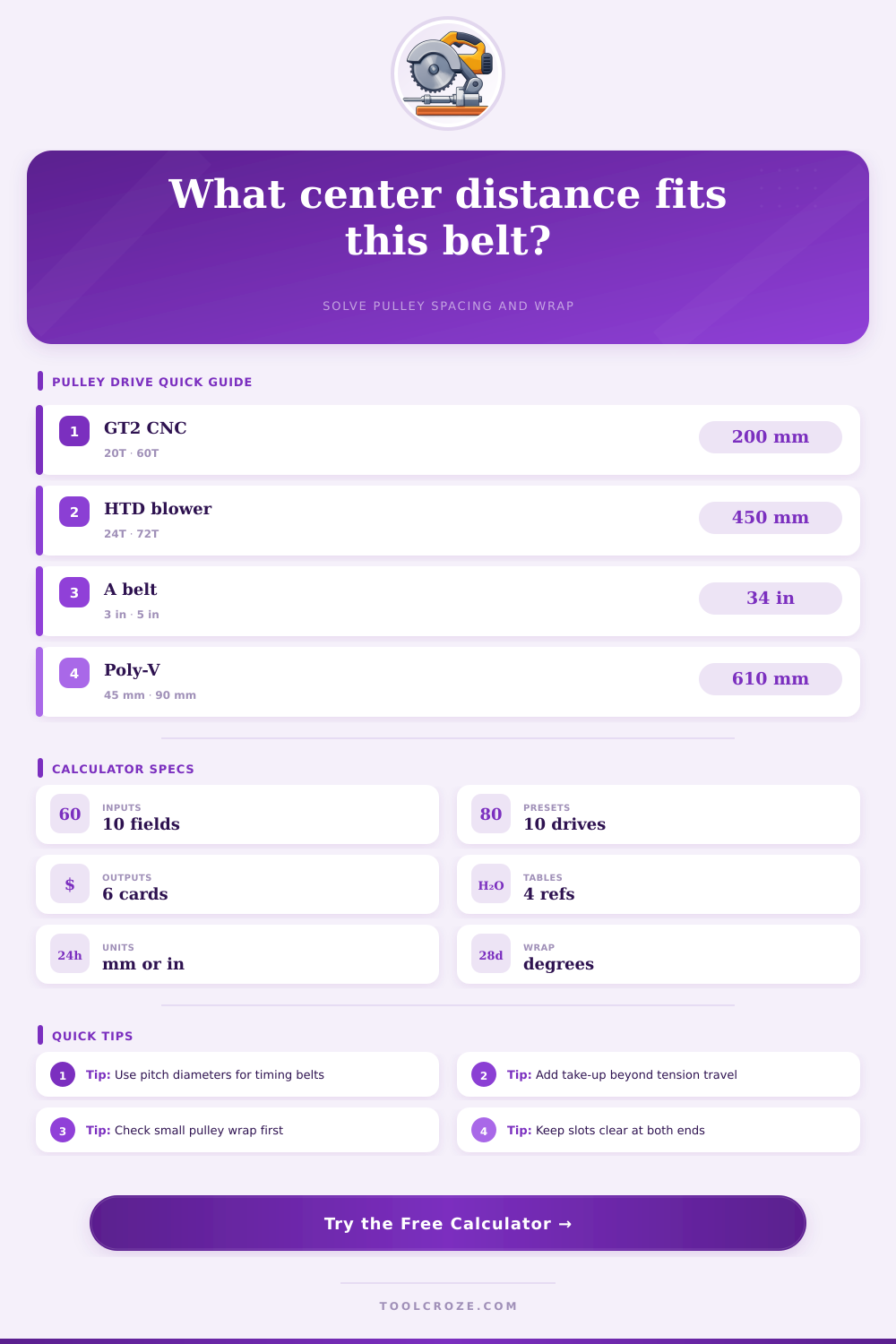
| GT2 CNC 20T to 60T | 200 mm pitch belt | 12.7 mm to 38.2 mm pitch dia | High ratio in a very compact axis drive |
| HTD 5M blower 24T to 72T | 450 mm pitch belt | 38.2 mm to 114.6 mm pitch dia | Wrap and center spacing affect torque transfer |
| A-section pump drive | 34 in effective length | 3 in to 5 in sheaves | Needs slot travel for install and retension |
| Poly-V fan drive | 610 mm effective length | 45 mm to 90 mm pulleys | Small-pulley wrap controls slip resistance |
| Crossed flat belt | 72 in pitch line | 6 in to 10 in pulleys | Crossed length correction uses pulley sum |
| Drive layout | Pitch length model | Wrap angle model | Use this when |
|---|---|---|---|
| Open belt | L = 2C + 1.5708(D+d) + (D-d)² / 4C | Small wrap = 180° - 2 asin((D-d)/2C) | Pulleys rotate the same direction |
| Crossed belt | L = 2C + 1.5708(D+d) + (D+d)² / 4C | Wrap = 180° + 2 asin((D+d)/2C) | Shafts rotate opposite directions with a belt twist |
| Equal pulley open belt | L = 2C + πD | Wrap is about 180° on each pulley | Fast estimate when diameters match |
| Timing tooth count | Teeth = belt pitch length / tooth pitch | Tooth engagement follows wrap angle | Checking if a catalog belt length is plausible |
Pull a belt too tight, it’ll snap off after a week. Leave it too loose and anytime you hit full torque the belt will slip out of place. There’s a sweet spot somewhere in between where the drive transfers power well and hums along quiet. That spot has nothing to do with intuition and a lot to do with geometry. Pull up the pulley center distance calculator above and let it run through math for you. But knowing what numbers represent makes all the difference when you’re standing on a grease-stained shop floor trying to keep a machine humming.
The first thing to do is find pitch diameter (not the outside diameter). This is key; certain type of belts ride at different positions. For example, V-belts sits in a groove within the sheave at what’s called its effective point… This isn’t the same as the rim. Likewise, timing belts bite into the sheave along the inside at their pitch line, again, not where you’d measure using outside diameter. Simply put: Measure outer edge of a pulley with calipers and enter it into the tool, and the resulting shaft spacing won’t match actual dimensions. You’ll never spin motor over, or if you do, the belt will be screaming tight or hanging loose. Find the right pitch reference. That’s all there is to it.
Key Steps for Belt Drive Setup
The wrap angle represent the amount of contact that the belt makes with surface of pulley. In general, the greater the wrap, the better it will grip. That’s why high ratio drives can sometimes be problematic because they use smaller pulleys. You’re literally fighting physics if your small pulley has a really low wrap angle, such as less than a hundred and forty degrees. Simply put, there isn’t enough surface area for belt to transfer the load without slipping. At this point, increasing the center distance (straightening out path a bit) or adding an idler pulley here is a necessity rather than an option. The tool show you the contact angle on each shaft so you can see whether or not you’ve got an inherently weak setup on the drive side.
Everything else come from belt length. Pick your belt and pick your pulleys. Geometry determines the center distance, which is basically set once you’ve chosen both parts. There’s no stretching a timing belt to make it work on a slightly wider gap. That’s what the calculator solves, and tells you exactly how far apart holes in the center of your motor mounts should of been drilled. It will also verify that your adjustment slot has enough travel for install. One misstep many people do is design the perfect drive on paper, then forget they’ll need to have some room to physically get the belt onto teeth. If the tool flags your slot range as short, that means you don’t have the wiggle room needed to tension the system correctly.
Speed of the belt. Faster belts makes more noise and wear out faster. Centrifugal force plus heat from high speed will eventually tear down the belt. The tool tells you an estimate of how fast the belt is moving in surface speed, which should give you a quick check before committing to your layout. Sometimes the ratio on paper might look right but the speed is too high, you may want a slower driver or bigger pulleys. You must trade off durability, speed, and size once you have all the variables together.
Lastly, think about the service factor. A CNC machine operates in a controlled, clean environment, under constant load with steady torque and speeds, whereas a mower deck see vibration, dirt and shock loading. This decision goes into the calculator which then adjusts the amount of tension allowance needed so that there’s sufficient adjustment range to account for what you might experience in the real world. It doesn’t look nice on a spreadsheet but don’t skimp out on your margins just because it does. Temperatures fluctuate, mounts shift, belts stretch. Extra room for adjusting is not wasted space; it is insurance against early failure.
A belt drive is an exercise in constraining things to make them fit. It is a balance of having enough slot travel so the drive can be installed. It needs enough wrap for good gripping and enough speed not to overheat. If you nail the spacing, then the drive becomes invisible and works silently so you can concentrate on something else. There’s no getting around the math, but the math also say you should pay attention to the geometry.