Pneumatic Stored Energy Calculator
Estimate compressed-air receiver energy from volume, gauge pressure, atmospheric pressure, temperature, expansion model, discharge orifice, risk category, and safety margin.
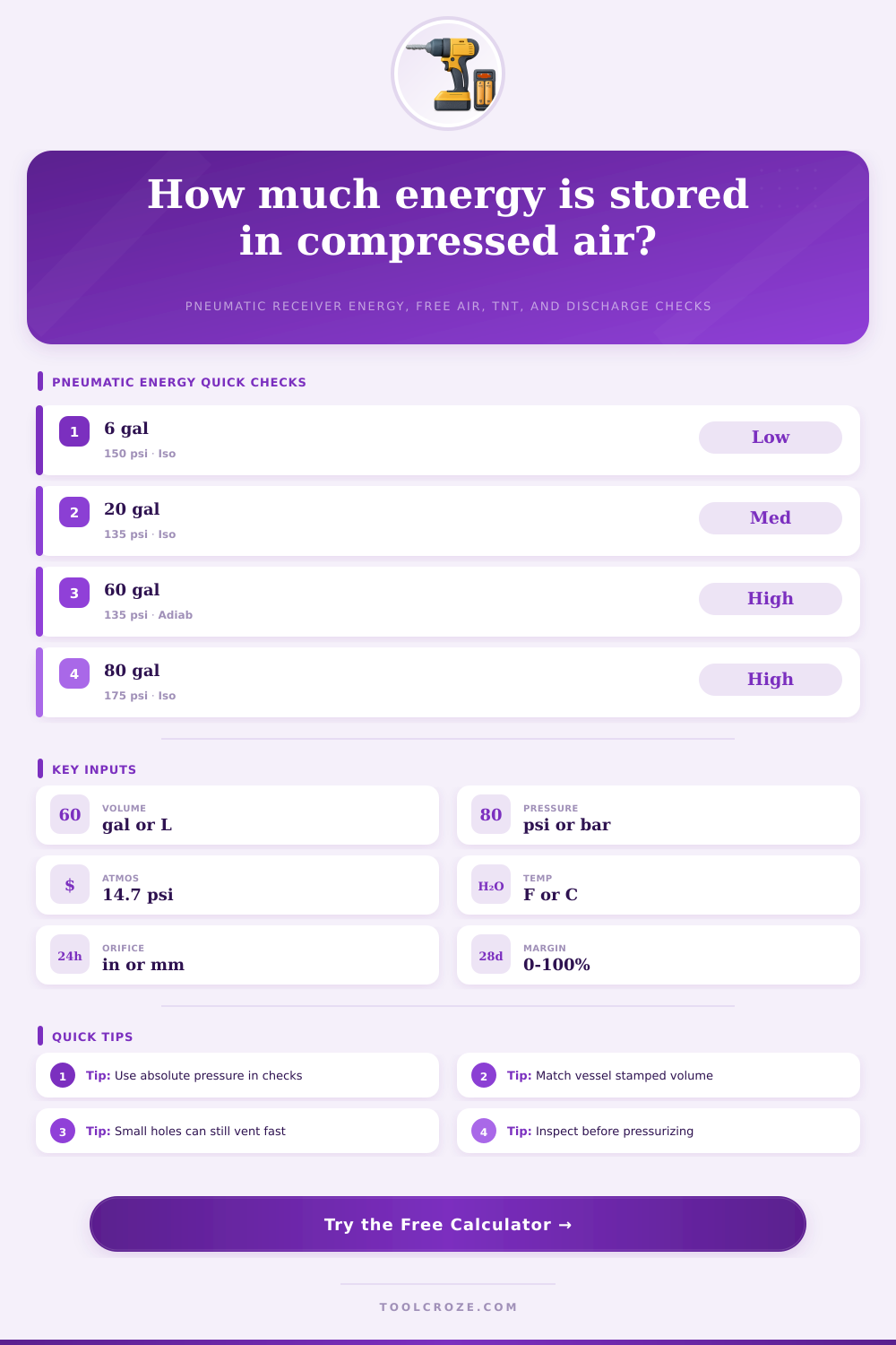
Pick a common receiver scenario, then adjust the stamped vessel volume, actual pressure, local atmosphere, temperature, orifice, and margin to match your setup.
Use the water capacity or stamped receiver volume, not compressor displacement.
The calculator converts volume to cubic meters internally.
Use gauge pressure above local atmosphere.
Pressure is converted to absolute pascals for energy formulas.
Use about 14.7 PSI at sea level, lower at altitude.
Temperature affects mass of air and orifice discharge rate.
Absolute temperature is used in the gas-flow calculation.
Isothermal usually gives the larger ideal stored work estimate.
Use the smallest likely opening, valve port, drilled hole, or failed fitting ID.
The area is converted to square meters.
Sharp holes are often near 0.60 to 0.65; rounded ports can be higher.
Risk category adjusts the displayed planning allowance.
Adds a user-selected buffer to the stored-energy planning number.
Formula Breakdown
| Expansion Model | Formula Form | Best Use | Typical Result |
|---|---|---|---|
| Isothermal | P1 x V x ln(P1/P0) | Slow expansion with heat transfer | Higher ideal work |
| Adiabatic | P1 x V x [1 - r^0.286] / 0.4 | Fast expansion with little heat transfer | Lower than isothermal |
| Conservative check | Higher model plus 10% | Screening unknowns before review | Planning buffer |
| Free air | (P1 - P0) x V / P0 | Air quantity and venting estimate | Volume at atmosphere |
| Gauge Pressure | Absolute Ratio | Energy Sensitivity | Practical Note |
|---|---|---|---|
| 90 PSI | 7.1 at sea level | Moderate | Common air tool receiver pressure |
| 125 PSI | 9.5 at sea level | High | Portable compressor upper range |
| 175 PSI | 12.9 at sea level | Very high | Typical two-stage shop pressure |
| 250 PSI | 18.0 at sea level | Extreme | Needs formal rated-vessel review |
| Opening Size | Area Change | Flow Behavior | What To Check |
|---|---|---|---|
| 1/16 inch | Small leak path | Can still be choked | Needle valves and drain ports |
| 1/8 inch | 4x 1/16 area | Fast blast near fitting | Quick couplers and small holes |
| 1/4 inch | 16x 1/16 area | Very rapid discharge | Regulator and hose bore |
| 1/2 inch | 64x 1/16 area | Severe local release | Valve body and manifold ports |
| Adjusted Energy | Band | Planning Meaning | Action Before Work |
|---|---|---|---|
| Under 1 kJ | Low | Small stored energy | Vent and verify zero pressure |
| 1 to 10 kJ | Moderate | Noticeable release hazard | Guard, isolate, and control access |
| 10 to 100 kJ | High | Serious stored energy | Use written lockout and barriers |
| Over 100 kJ | Critical | Major receiver hazard | Qualified pressure-vessel review |
As with all forms of energy storage, compressed air contain a form of stored energy. However, like all dangerous forms of stored energy, the energy stored within compressed air can also be dangerous if the compressed air is sudden released. The danger of compressed air does not come from the metal tank containing the air, but from the danger of the pressurized air within the tank.
To determine the danger of the tank, it is first necessary to estimate the amount of energy that are stored within the tank. This energy value will allow for the planning of any necessary maintenance or modification to the tank. The volume of the receiver tank is one of the primary factor to consider in the determination of the energy of the tank.
How to Calculate the Energy and Risk of a Compressed Air Tank
For many tanks, the user misreads the volume of the tank as the number stamped on the tank is the capacity of the tank for water, not the air volume of the tank. Thus, to ensure that the energy of the tank is correctly calculated, the calculator will convert any value for the receiver volume that is entered into the measurement of cubic meter. The second primary factor to consider is the pressure within the tank.
The pressure that should be used is the absolute pressure of the tank, not the gauge pressure of the tank. The atmospheric pressure of the air surrounding the tank (14.7 psi) will need to increase the gauge pressure, thus bringing the example pressure to approximately 150 psi. The calculator will make this adjustment automatically.
The third factor to consider is the temperature of the tank. Although the temperature will have a minimal effect on the energy if the temperature of the tank does not change, if the tank is within the sun or if the tank is within a refrigerated room, the energy within the tank will change. The mass of the air within the tank will decrease with an increase in the temperature of the tank.
Thus, the calculator will automatically change the temperature to absolute kelvin so that the ideal-gas law are maintained within the calculation. The fourth factor to consider is the type of expansion model of the air within the tank. If the air within the tank maintain a constant temperature as it is released from the tank, the energy of the tank will be higher than if the tank is adiabatic, which means that there is no transfer of heat from the tank to the air that is released from the tank.
The calculator allow for a more conservative estimate of the energy within the tank by allowing for a buffer to be created between the energy calculated from each of these expansion models. These models do not represent the complete engineering study of the tank, but they do create a number for the risk of the tank that can be discussed with those in the maintenance department. An additional factor to consider is the size of orifice in the tank and the coefficient of the discharge of the air from that orifice.
The size of the orifice will impact the velocity of the air discharged from the tank. The orifice and the coefficient of the orifice can estimate the initial flow rate of the air. This initial flow rate allows the user to understand if the danger from the tank is the energy of the tank or the initial jet of air discharged from the tank.
The blowdown time of the tank can be calculated from these same parameter. The blowdown time will show how long the air will continue to exit the tank after the initial rush of air. The risk category and margins are not considered to be a part of the physical calculation of the energy of the tank.
However, each risk category will have a multiplier that relate to the risk of the tank. For instance, a tank that is in a locked room may have a different risk level than a tank that is in a busy aisle within the facility. Additionally, a margin percentage can be applied to the energy of the tank to create a buffer for any error or issues with the tank.
Finally, the company will place the energy of the tank into one of four planning bands to determine if the tank require only a lockout procedure or if it requires a formal review of the pressure vessel. The theoretical calculation of the energy of the tank may not reflect the actual system. For instance, corrosion on the tank may reduce the margin of safety of the tank.
Additionally, relief valve on the tank may not function as expected if they have not been tested in recent times. Thus, if the energy of the tank is within a high or critical planning band, it is again recommended that the professional bring the tank into their inspection to ensure that it is in safe working order for the facility. Another consideration for the user of the calculator is to compare the energy of different receivers.
For instance, a 60-gallon receiver at 135 psi will contain more energy than a 20-gallon receiver at 135 psi. However, the energy is not mathematically proportional between the two tank. Additionally, two tanks of the same size may have different allowable working pressure.
Additionally, two tanks with different working pressures can end up in different risk categories for the facility. This comparison calculator will help the user to focus on the number entered rather than on there impressions of the risks of each tank. Finally, there are common mistake that many users of these calculations may make.
For instance, one common mistake is using the wrong unit for the measurements of the tanks. Another common mistake is using the gauge pressure of the tank rather than the absolute pressure of the tank. Additionally, individuals may use the displacement of the compressor instead of the volume of the receiver tank.
The displacement of the compressor and the volume of the receiver tank are not the same. However, an individual can avoid these mistakes by reading the nameplate or the test certificate that is attached to the receiver tank prior to performing these calculation. The goal of this calculation process is to create a common point of discussion between the various member of the maintenance and operational staff of the facility.
By agreeing on the energy value of the tank and the planning band to which it belong, the staff can have a clear discussion regarding the lockout procedure that should be performed and at what time the inspection of the tank should occur. Thus, the discussion of these variable is helpful for the facility in that it allows them to plan for the danger of the tank rather than to guess at that danger.