Pneumatic Cylinder Volume Calculator
Estimate cap-end extend volume, rod-end retract volume, free-air use per cycle, and total SCFM demand for single or multiple pneumatic cylinders.
Choose a real pneumatic motion scenario, then adjust bore, rod diameter, stroke, pressure, cycle rate, cylinder count, and allowance.
Inside diameter of the cylinder barrel.
Use 0 for rodless or cap-only volume checks.
Full travel distance for one extend or retract.
Gauge pressure at the valve or cylinder supply.
One cycle means one extend plus one retract.
Use the count that moves at this duty rate.
This changes retract-side swept volume.
Adds margin after pressure correction.
Calculation breakdown
| Bore and rod | Stroke | Actual cycle volume | Free air at 90 psig |
|---|---|---|---|
| 1 in bore, 0.3125 in rod | 4 in | 5.9 cu in | 0.024 SCF/cycle |
| 1.5 in bore, 0.5 in rod | 6 in | 19.1 cu in | 0.079 SCF/cycle |
| 2 in bore, 0.625 in rod | 8 in | 47.7 cu in | 0.197 SCF/cycle |
| 2.5 in bore, 1 in rod | 12 in | 108.4 cu in | 0.446 SCF/cycle |
| 3.25 in bore, 1 in rod | 12 in | 189.8 cu in | 0.782 SCF/cycle |
| 4 in bore, 1.375 in rod | 18 in | 397.7 cu in | 1.638 SCF/cycle |
| Gauge pressure | Absolute pressure | Free-air multiplier | Use case note |
|---|---|---|---|
| 60 psig | 74.7 psia | 5.08x | Low-force tooling |
| 80 psig | 94.7 psia | 6.44x | General automation |
| 90 psig | 104.7 psia | 7.12x | Common shop air |
| 100 psig | 114.7 psia | 7.80x | Higher-force actuators |
| 6 bar | 7.01 bar abs | 7.01x | Metric plant air |
| 7 bar | 8.01 bar abs | 8.01x | High supply header |
| Cylinder type | Extend volume | Retract volume | Volume planning note |
|---|---|---|---|
| Single-rod double acting | Full bore area | Bore area minus rod area | Most common air-use calculation |
| Double-rod cylinder | Annular area | Annular area | Balanced volume in both directions |
| Rodless actuator | Full bore area | Full bore area | Both directions use similar volume |
| Spring return cylinder | Powered direction only | Exhaust or spring return | Use extend-only mode when applicable |
| Guided slide | Usually full bore | Rod-end adjusted | Check manufacturer rod details |
| Total demand | Automation load | Header planning | Margin to check |
|---|---|---|---|
| Under 2 SCFM | Small clamp or ejector | Small branch line | Valve flow rating |
| 2 to 10 SCFM | Single slide or lift | Dedicated drop preferred | Tube length and fittings |
| 10 to 30 SCFM | Fast cycling cell | Check receiver recovery | Multiple simultaneous moves |
| 30 to 75 SCFM | Large bore machine | Review compressor capacity | Pressure sag at peak rate |
| Over 75 SCFM | Multi-cylinder station | Engineer storage and piping | Sequencing and surge volume |
Pneumatic cylinders converts the energy of compressed air into linear motion. The volume of air that a pneumatic cylinder consumes is not the same as the physical volume of the pneumatic cylinder. The reason for the difference between these two figure is due to the role of pressure.
Air that has a pressure of 90 psig or lower occupy less space then the same mass of air at atmospheric pressure. Thus, each stroke that the pneumatic cylinder make pulls in more free air than the physical displacement of the pneumatic cylinder. The volume of air that is pulled into the pneumatic cylinder is an important figure to determine the size of the air compressor that will supply the air to the pneumatic cylinder, the flow ratings of the pneumatic cylinder’s valves, and whether the pneumatic cylinder’s branch line can maintain the required air pressure during fast motion cycles of the pneumatic cylinder.
How Much Air a Pneumatic Cylinder Uses
The air volume calculator included on this page allow you to calculate the volume of air that a pneumatic cylinder will consume during each cycle in the unit of standard cubic feet. After you enter the diameter of the bore, the diameter of the pneumatic cylinder’s rod, the length of the stroke of the pneumatic cylinder, and the supply pressure of the air that is provide to the pneumatic cylinder, the calculator can determine the air volume that the pneumatic cylinder will consume. The calculator calculates the air volumes for the extend and retract strokes of the pneumatic cylinder separately.
The extend stroke of the pneumatic cylinder has a larger swept area then the retract stroke of the pneumatic cylinder. This is because pneumatic cylinders may operate in a mode where the cylinder both extends and retracts under load during a cycle. A double-rod actuator or rodless actuator will have the same air volume for both extend and retract strokes.
Single rod pneumatic cylinders does not have equal air volumes for both extend and retract strokes. However, the air volume calculator allow you to change from single rod to double rod to calculate the different air volumes. Furthermore, the air volume is calculated in standard cubic feet per cycle, which is a more conveniently unit of measurement for understanding the air requirements of a pneumatic system.
To calculate the standard cubic feet per cycle, the operator multiplies the air volumes by the ratio of the supply pressure to the atmospheric pressure. This allows engineers to more easily calculate the cubic feet of atmospheric air that will need to be compressed to supply the pneumatic cylinder with the required air at the supply pressure. To determine the average standard cubic feet of air per minute (SCFM) that will be required for the pneumatic cylinder, add the number of cycles per minute to the number of identical pneumatic cylinders in the system to the standard cubic feet per cycle figure.
This will indicate the total volume of air that will need to be supplied to the pneumatic system per minute. However, this total air volume figure is an estimate of the minimum volume of air that will be required. In the allowance field, add some extra volume for air that will leak past the pneumatic cylinder’s seals, the volume of air that will be contained within the pneumatic cylinder’s fittings, and for any drops in pressure due to friction in the system.
Ten percent is typically added as an allowance for a clean pneumatic system. However, if the pneumatic system includes long length of tubing or if the pneumatic cylinder’s valves are mounted far from the pneumatic cylinders, use fifteen or twenty percent as the allowance for the system’s losses. The reference tables included on the page show the standard cubic feet per cycle rate for various sizes of pneumatic cylinders with various strokes and supply pressures.
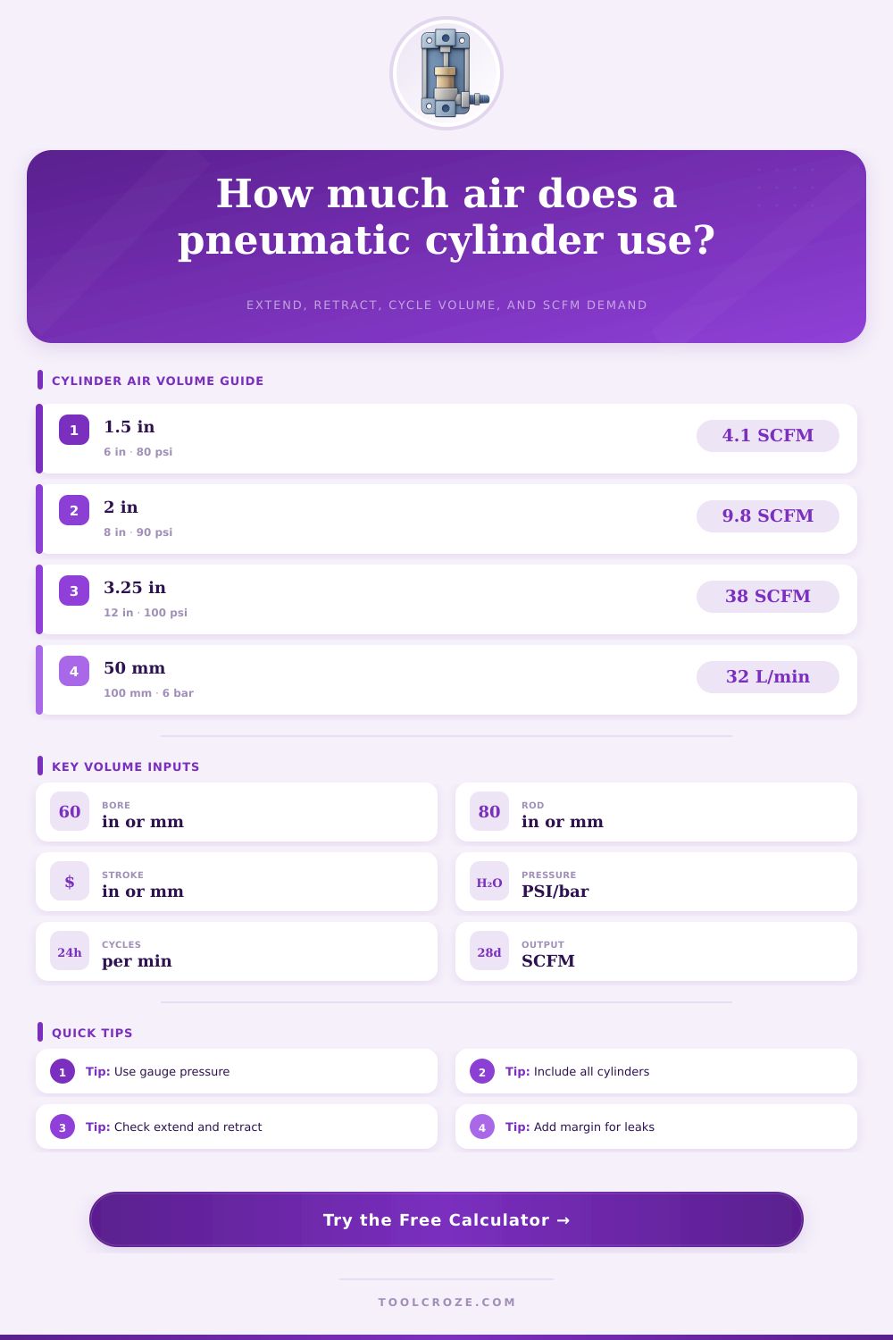
For instance, a pneumatic cylinder with a one and a half inch bore, a six inch stroke, and a supply pressure of eighty psig will have a demand of below five SCFM. However, if the pneumatic cylinder has a three and a quarter inch bore and is supplied with one hundred psig air, the demand for air will be several times higher. This higher demand result from the fact that the pneumatic cylinder has a larger area for the piston and the higher supply pressure increase the free air volume multiplier.
These tables allow you to estimate the demand of pneumatic cylinders without having to manually calculate each of these combinations of parameters. However, the air volume requirements calculated in these tables may be different from the actual requirements for the pneumatic system. This is because most pneumatic systems will have several pneumatic cylinder that are in simultaneous motion.
Each pneumatic cylinder will have a different supply pressure to each of the identical pneumatic cylinders. Furthermore, the supply pressure will be lower than the pressure in the header air tank due to the resistance of the pneumatic system’s components, such as the various fittings and tubing. The supply pressure will also be different for each pneumatic cylinder because the air will be moving at different rate to each pneumatic cylinder.
The rate at which the air is supplied to each pneumatic cylinder will affect the air supply rate at which each component of the pneumatic system will be moving. The calculated air volume is the steady-state value for the pneumatic cylinder. However, the rest of the pneumatic system will have to be able to absorb the pressure spikes that occur at the pneumatic cylinder when the pneumatic cylinder is extending or retracting at high rate.
Furthermore, the diameter of the pneumatic cylinder’s rod affect the volume of air that is required by the pneumatic cylinder. This is because pneumatic cylinders with thicker rods will have a smaller air volume for the retract stroke of the pneumatic cylinder. The retract stroke of the pneumatic cylinder is smaller than the extend stroke because of the presence of the pneumatic rod within the pneumatic cylinder.
Thus, pneumatic cylinders will extend at one rate with the application of air pressure but will return to their original position at a different rate because of the reduced available area to which the air can act. The air volume calculator account for this different between the extend and retract stroke air volumes by allowing the operator to change between single rod and double rod pneumatic cylinders. This allows for the volume to be calculated that takes into account the effect of the diameter of the rod on the volume of air that will be consumed by the pneumatic cylinder.
Finally, the temperature of the air that is supplied to the pneumatic cylinder and the elevation at which the pneumatic system is to be installed may play a role in the air consumption of the pneumatic cylinder. The temperature and elevation values are not included as fields in the air volume calculator. However, the colder the air that is supplied to the pneumatic cylinder, the more molecule of air will pass through the pneumatic system at a given gauge pressure.
Thus, hotter supply air will contain fewer molecules of air moving through the system than colder supply air. Furthermore, the elevation at which the pneumatic system is to be installed will affect the atmospheric pressure. Higher elevations has lower atmospheric pressures.
Thus, the pressure ratio will be higher at higher elevations with the same gauge pressure. However, the effect of temperature and elevation will only be felt in high altitude or if the pneumatic cylinder is being supplied with air at or near the maximum capacity of the air compressor that will supply the pneumatic cylinder with air. Read the safety note on this page twice before you begin to operate the pneumatic system.
The energy that is stored in the air within the pneumatic system can cause the pneumatic cylinder to extend even when the control valve for the pneumatic cylinder is in the center position. Furthermore, the pressure within the pneumatic system will act on any air that leak past the piston seals within the pneumatic cylinder. To make any adjustments to a pneumatic system, the supply of air to the pneumatic cylinder must be locked out, and all of the pressure that is stored within the pneumatic system must be released.
Air venting is the only surefire way to avoid being exposed to the hazard of pneumatic cylinders moving without control. Any warning about the pneumatic system’s components, such as pinch points, must be observed by the operator in addition to the warnings included with the pneumatic cylinder. The air volume calculator can be used as a tool to compare the specifications of various pneumatic cylinders that you are considering purchasing.
By altering the bore or the stroke of the pneumatic cylinder, you can view how these changes to the pneumatic cylinder will impact the volume of air that is required by the pneumatic cylinder. Furthermore, you can use the allowance field to view what may happen to the pneumatic system if the allowance is reduced to the minimum. This can help to decide which pneumatic cylinder will best fit into your pneumatic system and which variable can be set to their default values in the pneumatic system.
Using these iterations of the pneumatic cylinder specifications will allow you to avoid purchasing additional pneumatic system components and to avoid additional problems caused by overcharging the pneumatic air compressor. The values that are calculated for each pneumatic cylinder are only as useful as the assumption that you enter into the pneumatic cylinder air volume calculator. The bore and stroke of the pneumatic cylinder can be determined from the specifications of the pneumatic cylinder.
However, the supply pressure to the pneumatic cylinder may be lower than the header pressure of the pneumatic system due to the resistance of the components of the pneumatic system. Furthermore, while you may know the rate at which the pneumatic cylinder’s system is currently designed to cycle, the actual rate at which the pneumatic cylinder will move will vary from the calculated rate. Thus, the allowance field can be used to account for these uncertainty in the pneumatic system.
The specifications of the pneumatic cylinder as calculated by the pneumatic cylinder air volume calculator are only a planning specification. To verify the calculated air requirements of the pneumatic cylinder, you will have to purchase the pneumatic cylinder and install it into the system. At which point, a flow meter can be installed into the pneumatic system to measure the actual volume of air that is required by the pneumatic cylinder.