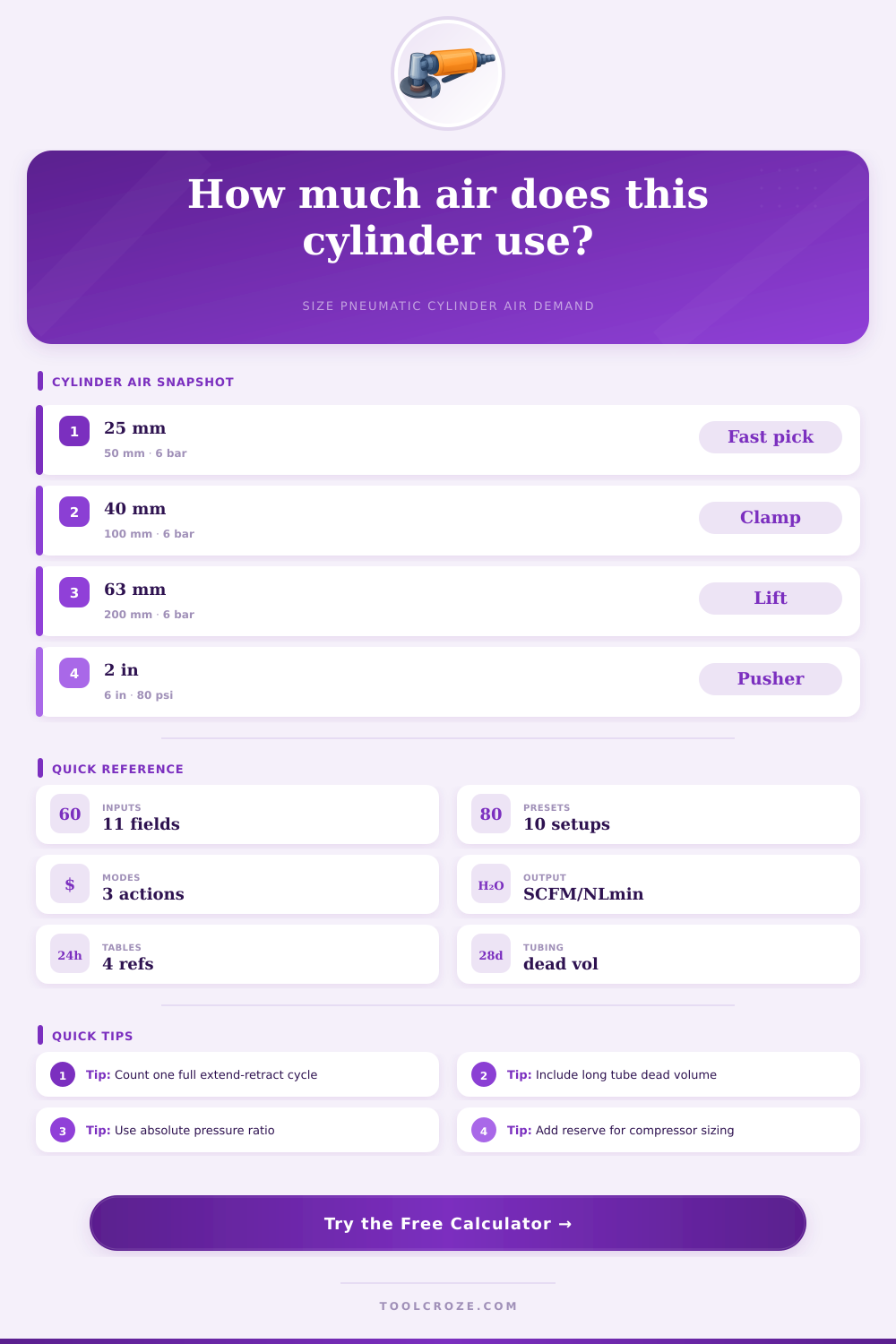
⚙ Air Consumption Calculator for Pneumatic Cylinder
Estimate free-air demand from cylinder bore, rod diameter, stroke, action type, pressure, cycle rate, tubing dead volume, duty, and number of cylinders.
📌 Pneumatic Cylinder Presets
⚙ Calculator Inputs
📋 Cylinder Spec Grid
📊 Reference Tables
| Bore and stroke | Rod | Cap volume | Typical use |
|---|---|---|---|
| 25 mm x 50 mm | 10 mm | 24.5 mL | Pick head, light stop, small ejector |
| 40 mm x 100 mm | 16 mm | 125.7 mL | Clamp, gate, short pusher |
| 63 mm x 200 mm | 20 mm | 623.4 mL | Lift, press assist, index stop |
| 2 in x 6 in | 0.625 in | 18.85 in³ | Packaging pusher or conveyor stop |
| Gauge pressure | Metric reference | Absolute ratio | Meaning |
|---|---|---|---|
| 60 psi | 4.1 bar | 5.08x | Free-air volume is about five times cylinder volume |
| 80 psi | 5.5 bar | 6.44x | Common plant air estimate |
| 90 psi | 6.2 bar | 7.12x | Higher force and higher air demand |
| 100 psi | 6.9 bar | 7.80x | Check cylinder, valve, and regulator ratings |
| Tube ID and length | Dead volume | Two ports | When it matters |
|---|---|---|---|
| 4 mm ID x 1 m | 12.6 mL | 25.1 mL | Small bore cylinders and fast cycling |
| 6 mm ID x 2 m | 56.5 mL | 113 mL | Medium cylinders with remote valves |
| 8 mm ID x 3 m | 151 mL | 302 mL | Large cylinders or long machine runs |
| 1/4 in ID x 6 ft | 5.9 in³ | 11.8 in³ | Imperial tubing on plant machines |
| Air result | Formula basis | Use it for | Common mistake |
|---|---|---|---|
| Per cycle | Swept volume x pressure ratio | Comparing cylinder sizes | Counting extend only on double acting |
| Per minute | Per cycle x cycles/min | Valve island and FRL load | Ignoring simultaneous cylinders |
| With reserve | Demand x reserve factor | Compressor and receiver sizing | Forgetting leaks and expansion |
| Tubing share | Dead volume / total volume | Deciding valve location | Mounting valves far from small actuators |
💡 Tips
Pneumatic cylinder are machines that move objects. These objects can be found in all types of factory, packaging plants, and assembly plants. The pneumatic cylinders requires a constant supply of compressed air in order to function.
The pneumatic cylinders will only function if the air compressor can provide the amount of air that the pneumatic cylinders requires. In addition to the size of the pneumatic cylinder, the amount of free air that the pneumatic cylinder consumes is also an important factor to consider. If the air compressor does not calculate the amount of free air that is required before purchasing the pneumatic cylinders, then the air compressor may run constantly or the machine may stall.
How Much Air Do Pneumatic Cylinders Need
The amount of air that the pneumatic cylinder consumes is dependent upon the geometry of the cylinder. If the pneumatic cylinder have a larger bore, it will require more air than pneumatic cylinders with smaller bores. Additionally, the pneumatic cylinder rod take up space within the cylinder on the retract side of the cylinder.
Thus, each side of the pneumatic cylinder does not consume the same amount of air. Single-acting pneumatic cylinders only pressurize one side of the cylinder so these types of cylinder will use half of the amount of air as double-acting pneumatic cylinders that perform the same tasks. The pressure at which the pneumatic cylinder operate is another factor that must be considered.
The pneumatic cylinder may receive gauge pressure at the control valve of the cylinder, but the air compressor will supply air at atmospheric condition. The ratio of the gauge pressure of the pneumatic cylinder to the atmospheric pressure of the air supply will turn the air volume in the cylinder into a larger volume of free air. Thus, if a few bar increases the pressure, the ratio of the pressures will increase rapidly.
Consequently, the factories that require air pressures of 100 psi will use more air than the machine builder had calculate for the pneumatic cylinder. Using atmospheric pressure in the calculation is a way to account for altitude and weather condition so that it isnt necessary to manually convert the units. Another factor to consider is the dead volume of the tubing and the pneumatic cylinder fitting.
Each time the control valve is shifted, the length of tubing must be refilled with air from the supply line before the piston can move within the pneumatic cylinder. In some case, the tubing for a pneumatic cylinder with a small diameter may have more volume than the pneumatic cylinder itself. The refill factor and field for dead-volume within the pneumatic cylinder can be used to calculate the amount of air required to refill the tubing.
Another consideration is the duty cycle and the number of pneumatic cylinders that are running at the same time. The pneumatic cylinder will consume less air if it is idled for half of the shift compared to the pneumatic cylinder that continuously move the object. Additionally, if many pneumatic cylinders are running at the same time, there demands on the air supply will increase.
If the air receiver tank is too small, this could cause problem for the system. Thus, field for a reserve factor are used in calculations so that for air leaks, future addition to the pneumatic system, or for the air compressors not delivering their full flow continuously, there is additional air supplied to the system. Many people size their air compressors according to the largest pneumatic cylinder in the facility.
The problem with this is that if additional machine are purchased later, the air compressor may not be able to supply the additional air requirements of those new machines. Thus, it is necessary to recalculate the requirement of air for the system. The air requirements will depend upon the duty cycle of each pneumatic cylinder, the lengths of the pneumatic tubing, and the pressure at the valve.
Additionally, moving the valve closer to the pneumatic cylinder will reduce the dead volume in the system. Thus, reducing the dead volume is more important than changing the pressure setting at which the pneumatic cylinder operate. If the cycle time is shortened for the pneumatic cylinder without changing the pneumatic cylinder geometry, the flow of air will have to increase in direct proportion to the speed at which the pneumatic cylinder operate.
Finally, ensuring that the pressure is checked at the valve rather than the air compressor outlet will provide the correct air pressure for the system. The target for engineer for pneumatic systems is not to use the lowest flow rate possible for the pneumatic cylinder. Instead, it is important to know how much air the pneumatic cylinder will use.
From this calculation, the designer can select the best air compressor, air dryer, and pneumatic piping system for the facility.