🔥 Plasma Cutting Speed Calculator
Estimate practical travel speed, arc time, kerf removal, and pierce timing from plate thickness, amperage, gas quality, and cut intent.
📌 Job Presets
⚙ Cut Setup
🎯 Results
📈 Material And Spec Comparison
📊 Reference Tables
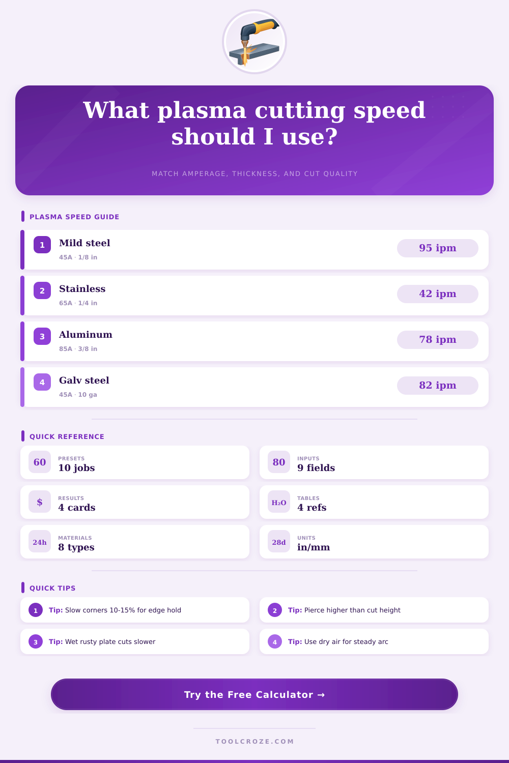
| Material | Reference Thickness | Reference Amps | Chart Speed |
|---|---|---|---|
| Mild steel A36 | 1/8 in | 45A | 95 ipm |
| Stainless 304 | 1/8 in | 45A | 52 ipm |
| Aluminum 5052 | 1/8 in | 45A | 118 ipm |
| Galvanized steel | 10 ga | 45A | 82 ipm |
| Painted mild steel | 10 ga | 45A | 76 ipm |
| AR400 plate | 1/4 in | 85A | 42 ipm |
| Expanded metal | 14 ga | 30A | 160 ipm |
| Copper alloy | 1/8 in | 65A | 28 ipm |
| Nozzle Range | Typical Kerf | Best Thickness Window | Notes |
|---|---|---|---|
| 30A | 0.055 in | 16 ga to 1/8 in | Light sheet, mesh, detailed tabs |
| 45A | 0.060 in | 10 ga to 1/4 in | General table work and repair plate |
| 65A | 0.070 in | 3/16 in to 3/8 in | Stable production speed on common plate |
| 85A | 0.082 in | 1/4 in to 3/4 in | Higher pierce energy and stronger bevel control |
| Thickness | Pierce Height | Cut Height | Typical Dwell |
|---|---|---|---|
| Up to 1/8 in | 0.12 in | 0.06 in | 0.2 to 0.4 s |
| 3/16 in | 0.15 in | 0.06 in | 0.5 to 0.7 s |
| 1/4 in | 0.18 in | 0.06 in | 0.8 to 1.1 s |
| 3/8 in | 0.20 in | 0.07 in | 1.2 to 1.6 s |
| 1/2 in | 0.24 in | 0.08 in | 1.7 to 2.4 s |
| Common Job | Material | Practical Setup | Travel Speed |
|---|---|---|---|
| Trailer gusset set | 1/4 in mild steel | 65A dry air, production | 42 to 48 ipm |
| Food-grade bracket | 3 mm stainless | 45A nitrogen, fine cut | 34 to 39 ipm |
| Fuel cell cover | 6 mm aluminum | 45A dry air, production | 40 to 48 ipm |
| Wear strip blank | 1/4 in AR400 | 85A oxygen, production | 36 to 44 ipm |
💡 Practical Notes
Plasma cutting require the management of travel speeds because travel speed affect plasma cutting quality and the amount of dross that will remain on the metal after the cutting process. If plasma torch travel speed are too fast for the metal thickness, the plasma arc will not be able to fully penetrate the metal, and fast travel speeds will result in a wavy edge to the cut metal with dross clinging to the bottom of the cut. If plasma torch travel speed is too slow for the metal thickness, the plasma arc will melt too much of the metal, and slow travel speeds will result in the metal become a puddle of liquid metal.
Thus, the operator must adjust travel speed according to the thickness of the metal that is being cut and the outputs of the plasma torch. Material type is one of the main factor to consider that will affect travel speed. Mild steel is the most common metal that will be cut with air plasma torches, and mild steel will allow for a consistent travel speed with a 45-amp plasma torch setup.
How to Set the Right Speed for Plasma Cutting
Stainless steel is a different metal that require nitrogen gas to prevent the edges of the cut stainless steel from oxidizing. Aluminum metal will behave differently than steel due to the low density of aluminum metal, which allows the plasma arc to travel faster through the metal, but which also requires more precise height control for the torch to avoid dive into the metal. Each of these different metals will react to heat in different ways, thus requiring different travel speed for optimal results with each metal type.
Amperage is another significant factor in determining travel speed. Amperage determine the power of the plasma arc, and the higher the amperage of the plasma torch, the higher the travel speed that can be attained. For instance, a 65-amp nozzle can be used to cut quarter-inch plate at a specific travel speed, but an 85-amp nozzle with oxygen gas will allow for both an increased travel speed and pierce reliability when cutting denser metals like AR400 wear plate.
A mathematical formula relate amperage and travel speed, and this formula accounts for the non-linear way that travel speed can change with metal thickness. Additionally, voltage will impact plasma arc stability, and the height of the plasma torch relative to the metal will impact cutting; if the torch is too high relative to the metal thickness, the plasma arc will bevel the metal, but if the torch is too low relative to the metal thickness, electrical short will occur. The quality of the gas that is used in the plasma torch will also impact the cutting process.
If the air used to charge the compressor that supplies the plasma torch contain moist air, the plasma arc may destabilize and the moist air will reduce the metal cutting speed by approximately 10 percent. Using oxygen gas will improve cutting speed of steel metal, but nitrogen gas will improve the cutting of stainless steel. Thus, the quality and type of gas will impact the stability of the plasma arc, which must be maintained within an optimal range for the quality of the plasma cut; if gas type and quality are not correctly adjusted, the user will need to alter travel speed to accommodate.
The total time require for a plasma cutting job will be determined by the travel speed, the number of pierce that are made into the metal, and the total length of the cut. Each time that the plasma torch pierce the metal, the torch must remain in that location for a specific length of time; these pierce delays will impact the total time required to complete the cutting job. Thus, arc time must be separated from pierce delay to determine the total productivity of the plasma cutting machine.
Additionally, the operator can also calculate the kerf removal rate to determine the productivity of the plasma cutter itself. Different metals require different travel speed adjustment to achieve the best results. Metals that are expanded allow for low amperage settings to the metal to prevent the metal from washing out of the plasma torch, but high severance speeds are required to prevent the metal from melting through the plasma torch.
Metals that contain metal paint or that are galvanized have a coating that will cause spark in the plasma torch and slow the plasma arc, thus requiring the paint to be ground off of the metal prior to plasma cutting. Additionally, when plasma torches are used to cut corners in metal, the torch travel speed should be slowed by 10 to 15 percent to account for the metal torch swinging too wide when cutting those corner. Lastly, if the metal to be cut is wet or if the air quality is poor in the environment in which the metal cutting will occur, the cutting speed should be slowed to 20 percent of the initial estimated cutting speed.
Height control of the torch will impact both travel speed and quality of the plasma cut. If using mechanized cutting table, the torch height should be set to 0.06 inches to ensure quality cuts; with hand torches, a consistent height must be maintained to avoid spatters on the metal. Additionally, traveling at a speed 10 percent slower than the maximum travel speed of the torch should create a safety margin; the slower travel speed will allow for more even metal cutting.
Finally, there are different cutting mode to select from; production mode will balance cutting speed and quality, severance mode will prioritize cutting speed above quality, and fine cut mode will prioritize quality of the metal edges over cutting speed. Overall, each of these factor will have an impact on cutting speed and the parameter for which the torch should be adjusted.