Pipe Miter Joint Calculator
Lay out branch-to-run saddle cuts with pipe OD, intersection angle, root gap, bevel prep, and wrap-template points for field marking.
⚙Pipe Fitting Presets
📐Joint Inputs
📊Calculated Saddle Layout
📝Wrap Template Points
| Point | Clock Position | Wrap Distance | Cut Height | With Gap | Bevel Setback |
|---|---|---|---|---|---|
| Calculate to generate saddle wrap points. | |||||
🛠Material and Spec Comparison
📏Reference Tables
| NPS Size | Actual OD | Sch 40 Wall | Common Branch Use |
|---|---|---|---|
| 1 in | 1.315 in / 33.4 mm | 0.133 in / 3.38 mm | small drain, air, sprinkler outlet |
| 1-1/2 in | 1.900 in / 48.3 mm | 0.145 in / 3.68 mm | handrail, light process branch |
| 2 in | 2.375 in / 60.3 mm | 0.154 in / 3.91 mm | common branch on 4 in to 6 in run |
| 3 in | 3.500 in / 88.9 mm | 0.216 in / 5.49 mm | lateral wye or equipment tie-in |
| 4 in | 4.500 in / 114.3 mm | 0.237 in / 6.02 mm | header branch or equal tee layout |
| 6 in | 6.625 in / 168.3 mm | 0.280 in / 7.11 mm | large run with reducing saddle branch |
∠Intersection Angle Reference
| Centerline Angle | Joint Name | Template Behavior | Field Check |
|---|---|---|---|
| 90 deg | straight tee saddle | balanced high-low profile | low points land at pipe springline |
| 60 deg | sloped branch | one side stretches noticeably | verify long side before cutting |
| 45 deg | standard lateral wye | long saddle tail and acute heel | add fit-up marks at quarters |
| 30 deg | low-angle merge | large axial height change | use more wrap divisions |
🔥Weld Prep Reference
| Pipe/Tube Fit-Up | Typical Bevel | Root Gap | Root Face Land |
|---|---|---|---|
| Carbon steel Sch 40 butt branch | 37.5 deg | 1/16 to 1/8 in | 1/16 in |
| Thin stainless tube | 0 to 30 deg | 0 to 1/16 in | small square land |
| Heavy wall pressure pipe | 30 to 37.5 deg | per WPS | per WPS |
| Handrail or exhaust tube | 0 to 15 deg | tight cope | deburred edge |
🧮Template Resolution Reference
| Divisions | Degree Step | Best Use | Layout Note |
|---|---|---|---|
| 8 | 45 deg | rough cut then grind | fastest shop layout |
| 12 | 30 deg | small pipe wraps | fits narrow paper strips |
| 16 | 22.5 deg | general pipe fitting | good default accuracy |
| 24 | 15 deg | acute laterals | smoother long tail curve |
| 32 | 11.25 deg | large OD templates | best for plasma tracing |
💡Pipe Layout Tips
When cutting a branch off a straight run pipe you’re faced with a seemingly straightforward geometry: A straight run pipe with a branch coming out at an angle from it. Almost never will that angle be exactly 90 degrees. What happens is that the point where those two cylindrical surface meet forms a saddle shape. This saddle shape changes based off the angle the branch intersects as well as the diameters of each of the two pipes. Getting that curve right makes the branch slide on nicely without huge gaps or gouges that would weaken the weld and require lots of filler. It’s the difference between a nice fabrication job vs. It is one that needs a bunch of filler to hide poor fit-up.
All this trigonometry stuff projects the saddle curve on a flat template. All you need to do is plug in the angle where the branch intersects the run pipe and the outside diameter for both. The calculator does the rest. It split up the circumference of the branch into points, calculates the cut’s height at each point, and spits out a list of coordinates. These are then transferred to paper or, more likely, right onto the pipe.
How to Cut Pipes and Make Good Welds
This reference table shows the named size of common pipe sizes and what actual outside diameter is. What’s the difference? Well, just because something is called a 2-inch pipe doesn’t mean it’s two inches across. In fact, it’s 2.375 inches. If you try to use the nominal size instead of the actual outside diameter, you’ll end up with a gap, one that increases with every turn around the pipe.
Finally, weld quality is greatly affected by root gap. When welding two pieces together with one inside the other (as in a branch into a run), you must have room for the weld metal to flow through. With this tool, you can specify a root gap, and it will offset that value from where the branches should meet theoreticaly. That way, when you push the branch against the run, you’ll have just enough room for it to fuse properly. Too little and the branch sits too tightly; too much and you’ll use up too much weld material and are more likely to have distortion issues.
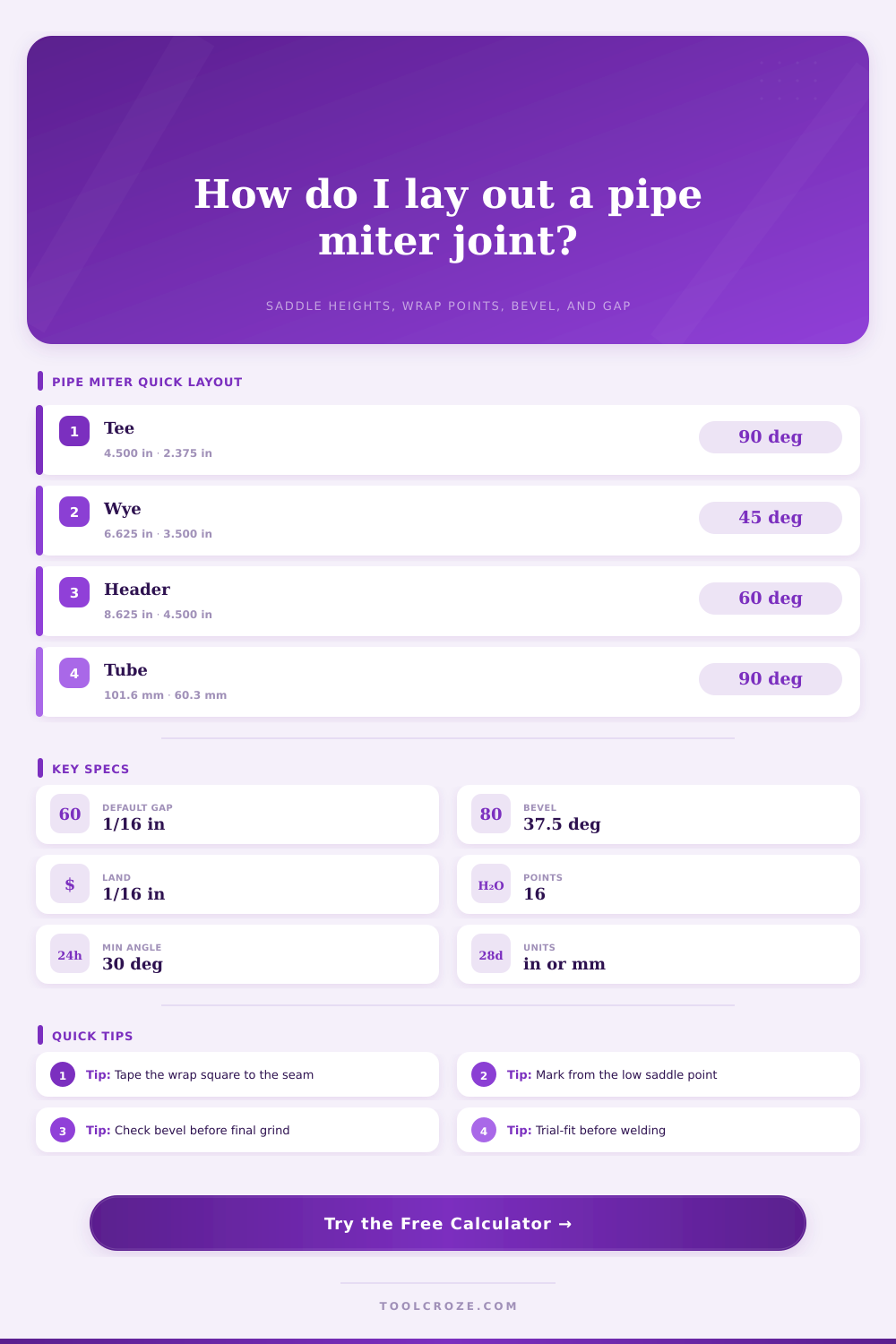
The layout is also affected by the bevel prep. According to most structural welding specifications, a bevel angle of 37.5 degrees with a small amount of land remaining on the root side are required. To compensate for this bevel, the calculator gives you setback measurements. These indicate where on your cut lines to begin preparing your bevel so the finished beveled surface matches up properly with the curve of the saddle. Small details, yes, but they do matter. If you do not consider the shape of the bevel, it may cause an uneven root face. This can lead to uneven penetration and possible defects in the weld area.
Real-world field conditions rarely are as neat and tidy as the textbook geometry. Pipes aren’t true circles, in fact rough handling or transport makes them even more oval than when they were new. A paper template made for wrapping assumes a perfect circle. You wrap it on your slightly oval pipe, and the points won’t meet perfectly. Make a mark of where the points don’t meet well and go from there. Start with marking the low and high points first and work out from there. Grind out the top if it’s tight. Mark the new line if it’s too loose on the sides. The template is not a hard and fast rule, but just a starting point.
You have to choose how many divisions to use on the template points. That’s a matter of balancing accuracy against the amount of time it takes to make those points. The more divisions you use, the closer you get to the actual shape, but slower it will go. The larger the pipe’s diameter and the shallower the angle, the more divisions is needed to catch small rises and falls in the height. Steeper angles or smaller diameter pipes might be done with less points. It’s about finding the sweet spot of getting as accurate as needed without wasting too much time making marks versus actualy grinding.
Remember safety is always first with this kind of work. Cutting and grinding pipe will have sharp edges, sparks and heat. Use appropriate hand and eye protection. Make sure your tool is rated for the type of material you’re cutting. If you are not careful, aluminum can gum up a steel blade. Stainless steel should be cut on clean surfaces to prevent contamination.
Your care and skill will do it right but the math would of gotten you close. The weld looks like it was never there; a good saddle joint is seamless in the final product. No voids. No excess. A smooth flow. The welder adds the finish. The calculator provides the plan. The grinder adjusts. Numbers first. Fit second. Grind third. That’s the rhythm of quality fabrication. What you see on screen as the arc bridges geometry to reality has to be what you calculated on screen: the curve you weld must mirror the curve you calculated.