Pin Joint Structure Calculator
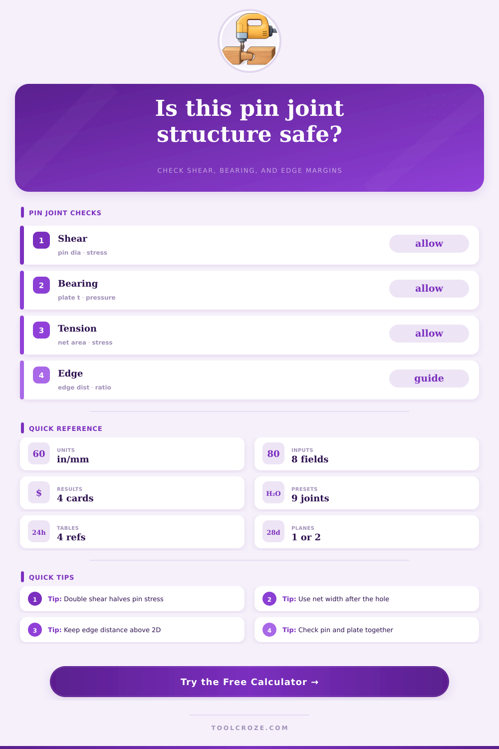
Check a pinned plate, lug, clevis, truss node, or bracket joint for pin shear, plate bearing, net tension, edge distance, and governing safety factor.
Each preset fills the structural inputs and runs the calculation so you can compare typical pin-connected details.
Pin Joint Results
| Plate material | Yield guide | Allowable tension guide | Bearing guide |
|---|---|---|---|
| A36 structural steel | 36 ksi | 21.6 ksi | 32.4 ksi |
| A572 grade 50 steel | 50 ksi | 30.0 ksi | 45.0 ksi |
| 304 stainless steel | 30 ksi | 18.0 ksi | 27.0 ksi |
| 6061-T6 aluminum | 35 ksi | 21.0 ksi | 31.5 ksi |
| Structural glulam timber | 2.4 ksi | 1.2 ksi | 1.8 ksi |
| Pin grade | Tensile guide | Shear guide | Typical use |
|---|---|---|---|
| Mild steel pin | 58 ksi | 34.8 ksi | Light brackets, hinges |
| Grade 5 steel pin | 120 ksi | 72.0 ksi | Clevises, machinery links |
| Grade 8 steel pin | 150 ksi | 90.0 ksi | Compact high load joints |
| 304 stainless pin | 75 ksi | 45.0 ksi | Outdoor corrosion resistance |
| Bearing bronze pin | 40 ksi | 24.0 ksi | Low speed pivots |
| Nominal pin | Close hole | Preferred edge | Single shear area |
|---|---|---|---|
| 1/2 in | 17/32 in | 1.0 in+ | 0.196 in² |
| 5/8 in | 21/32 in | 1.25 in+ | 0.307 in² |
| 3/4 in | 13/16 in | 1.5 in+ | 0.442 in² |
| 1 in | 1-1/16 in | 2.0 in+ | 0.785 in² |
| 1-1/4 in | 1-5/16 in | 2.5 in+ | 1.227 in² |
| Joint detail | Primary check | Common weak point | Good starting ratio |
|---|---|---|---|
| Single plate lug | Pin shear and bearing | Plate bearing at hole | t ≥ 0.4D |
| Double clevis | Net tension in center lug | Unequal fork fit-up | 2 shear planes |
| Gusseted truss node | Load line eccentricity | Net section tear-out | edge ≥ 2D |
| Pivot hinge | Bearing pressure | Pin wear over cycles | hole + 1/32 in |
| Timber connector | Embedment bearing | Splitting near edge | edge ≥ 4D |
A pin joint are created when a pin is placed inside an holes of the two plates to create a pivot point for the plates. A pin joint is subjected to several different type of stress. One type of stress is shear stress, which is the force that attempt to slide the pin apart.
Another type of stress is bearing stress, which is the crushing force that the curved surface of the pin makes contact with the interior wall of the hole in the plate. The third type of stress is net tension stress, which is the force that may cause the plate to snap apart along the section of the plate where the hole was drilled. Each of these types of stress must be evaluated to determine whether the pin joint may fails.
Pin Joints and What Makes Them Strong
The relationship between the pin and the plate is one of a factors to consider in the strength of the pin joint. If the pin is much stronger then the plate, the pin may remain intact while the plate fails. For example, if a high strength steel pin is placed into an aluminum plate, the steel pin will not break, but will crush the aluminum plate into an oval shape.
The strength of the pin is higher than the strength of the aluminum plate. The strength of both the pin and the plate must be matched to ensure the pin joint function in the intended way. The way that the pin joint is configured will change the way that it resist the applied load.
One configuration include single shear joints, in which the pin has only one plane to resist the load applied to the pin joint. In the other configuration, double shear joints, the pin is placed between two plates, such as in a clevis joint or a fork. The double shear joint configuration is considered more stronger than the single shear joint configuration because there are two planes of metal that help to resist the force of the load.
Because the double shear joint configuration is stronger, the diameter of the pin can be smaller if double shear joint are used. The distance between the hole in the plate and the edge of the plate is a measurement that is necessary to take in the formation of a pin joint. This distance is referred to as an edge distance.
If the edge distance is too short, the pin may cause a tear-out failure of the plate. A tear-out failure is one in which the pin push on the plate causing the plate to tear out through the side of the plate. In order to avoid this type of failure, the edge distance must be at least twice the diameter of the pin.
If this specification are not met, the plate will fail at the edge of the hole. The angle of the load that is applied to the pin joint is another factor that will change the stress that is placed on the pin joint. The force of the load is often not applied in a straight line to the pin joint.
If the load is applied at an angle to the pin joint, it will create additional stress on the pin joint. This angle must be accounted for when the pin joint is being design. Finaly, a safety factor must be selected for the pin joint.
The safety factor is used to create a buffer for the mathematical calculation requirements for the pin joint to account for the possibility of defect in the metal, or overexertion of the pin joint by the attached object. If the pin joint is for a low-risk application, a low safety factor can be used. However, if the pin joint is to be used in a high-risk application, a high safety factor will be used for the pin joint to ensure it can handle more force than that which is expected of the pin joint.
Each of these factor will ensure that the pin joint remains stable and doesnt become a point of failure in the structure.