🧪 O-Ring Stretch Calculator
Check free ID against gland diameter, target stretch, cross-section shrink, elastomer limit, temperature swell or shrink, and tolerance allowance.
📌 Presets
⚙ Calculator Setup
📊 Results
🧪 Material / Stretch / Spec Grid
📚 Reference Tables
| Application | Typical stretch | Upper review | Design note |
|---|---|---|---|
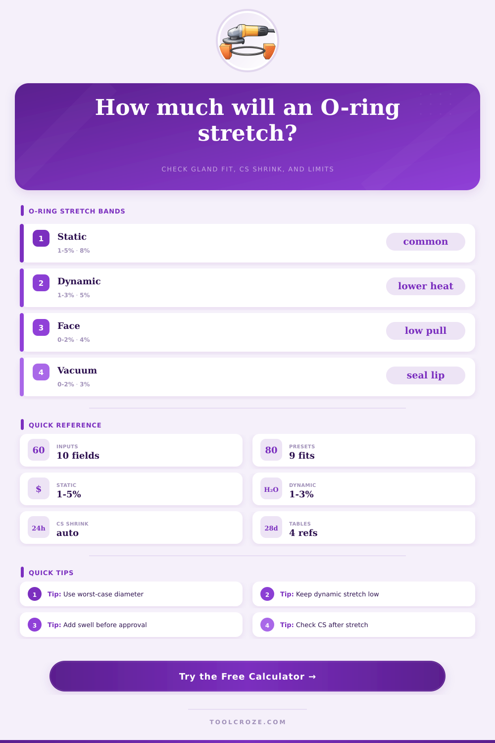
| Static radial gland | 1% to 5% | About 8% | Common ID stretch range for seated hardware. |
| Dynamic radial gland | 1% to 3% | About 5% | Lower stretch helps limit friction and heat. |
| Face seal groove | 0% to 2% | About 4% | Use only enough pull to retain the ring. |
| Vacuum cover seal | 0% to 2% | About 3% | Keep the ring seated without thinning the lip. |
| Material | Design limit | Thermal expansion | Stretch comment |
|---|---|---|---|
| NBR 70A | 8% | 0.00018 / °C | Useful baseline for oil and hydraulic service. |
| FKM 75A | 6% | 0.00016 / °C | Check hotter service and compression set. |
| EPDM 70A | 8% | 0.00020 / °C | Often used in water service; confirm fluids. |
| Silicone 70A | 5% | 0.00028 / °C | High thermal change, low stretch preferred. |
| HNBR 80A | 6% | 0.00017 / °C | Higher pressure duty with tighter review. |
| PTFE encapsulated | 3% | 0.00012 / °C | Rigid jacket, avoid installation over-stretch. |
| Check | Formula | Good sign | Risk sign |
|---|---|---|---|
| Stretch | (Gland ID / free ID - 1) x 100 | Inside application band | Above material limit |
| CS shrink | 1 - 1 / square root(ratio) | Small CS thinning | Squeeze loss likely |
| Thermal shift | Material CTE x temp change | Reviewed with swell | Cold shrink raises pull |
| Worst case | Max gland / min free ID | Still below limit | Limit exceeded |
| Nominal size | Free ID | Cross-section | Common review |
|---|---|---|---|
| AS568-010 | 0.239 in | 0.070 in | Small static ports |
| AS568-112 | 0.487 in | 0.103 in | Spools and plugs |
| AS568-214 | 0.984 in | 0.139 in | Hydraulic bores |
| AS568-325 | 1.975 in | 0.210 in | Large covers |
| M20 x 2.5 | 20.0 mm | 2.5 mm | Pump glands |
| M50 x 3.5 | 50.0 mm | 3.5 mm | Face grooves |
💡 Tips
This calculator estimates O-ring stretch from free ID, gland diameter, tolerance stack, material limit, temperature, and swell. Use it to flag excessive pull before final seal review.
O-ring stretch are the measurement of how much an O-ring is pull during installation. Because O-ring stretch is a critical factor in the function of an O-ring, using too much O-ring stretch can lead to seal failure. While the O-ring may appear to be function properly during installation, the O-ring may begin to leak after the seal has been subject to changes in temperature or fluid.
Often it is difficult to determine the O-ring stretch that an O-ring will experience based off the technical drawings of the component alone. O-ring stretch is actualy influence by a number of different variables. Variables to consider include the free inside diameter of the O-ring, the diameter of the gland or the shaft that the O-ring will fit over, the cross section of the O-ring, and the limits of the elastomer material itself.
How to Calculate and Check O-Ring Stretch
The temperature to which the O-ring is exposed can cause the O-ring to expand or contract. Additionally, fluid that are exposed to the O-ring can cause the O-ring to swell or shrink in size, which will also change the tension of the O-ring. Each of these variable can be accounted for in the calculator.
The free inside diameter and the gland diameter of the component must be entered into the calculator. Fields for considering the manufacturing tolerance of each of these components exist. Additionally, the user must select the material of the O-ring in order to account for the limits that the elastomer can endure in regard to stretch and temperature change.
An extra field is provided to account for the cross-section shrink of the O-ring that result from stretch, and another field is provided for the swell of the O-ring due to the fluids that are exposed to it. Different application will feature different bands of O-ring stretch that are permitted. For instance, static gland will allow for more O-ring stretch than dynamic glands.
Similarly, face seal and vacuum covers will require less O-ring stretch than other type of seals. These bands are provided to help indicate the various way that an elastomer can fail under excessive O-ring stretch or thinning of the O-ring. When the O-ring is stretched, the cord diameter of the O-ring will shrink.
Fields are provided to account for any compression set of the O-ring, which the supplier of the O-ring can cause. Additionally, you can enter the swell of the O-ring due to the fluids into the calculator to help reveal if the swelling compensates for the thinning of the O-ring to help hide excessive O-ring stretch. The table provided on the calculator can be used to cross-check the calculation performed by the calculator.
One set of reference table provides the stretch ranges for different type of glands. Other reference tables include the design limit for various elastomers. Additionally, the table provides the coefficients that are applied to determine the changes to the O-ring due to changes in temperature and fluids.
These number do not need to be memorized, but reviewing these tables alongside the O-ring calculation will help to provide an understanding of the reasons for the differences between, for example, silicone O-rings versus HNBR O-rings. It is common for individuals to treat O-ring stretch as a single, specific value. Instead, one should consider O-ring stretch within a range.
Calculating the worst-case scenario for O-ring stretch will help to ensure that the stretch accounts for the possible tolerance of both the O-ring and the gland. Additionally, if the O-ring must be stretched during installation to fit over a component, the pull factor can be used to account for this. Both temperature and fluids will continue to have an effect on the O-ring after it is installed into the component.
For instance, if the O-ring is installed at 3% stretch at room temperature, the components may warm over time and the elastomer material can expand. Cold service may induce a shrinkage of the O-ring material. Additionally, exposure to fluids can cause the O-ring compound to swell, which will relax the tension created by the O-ring during installation.
Other fluids can cause the O-ring to shrink due to the extraction of plasticizers from the elastomer. The limits of the elastomer compound can change with time. For instance, softer compound can better take O-ring stretch before the material begins to crack, but they tend to take a permanent set more quickly.
Hard compound tend to not set, but will fail in the same way if the stretch of the O-ring exceeds the limits for that compound. The verdict field will show the result of the calculation. Good indicates the result are within the specification limits.
Review or Marginal indicates that the O-ring components are near the limit of their design. Revise indicates that the component of the seal are beyond the limits for that compound. While this calculator can provide an estimation of O-ring stretch limits for most applications, there are some factors that are outside of the scope of this calculator, such as compression set after many years, ozone cracking, etc. However, by removing the arithmetic uncertainty in calculating O-ring stretch, engineer can focus upon engineering questions of the O-ring.
Therefore, it is recommended that such a calculation should of been performed with the nominal and worst-case scenario to ensure that the stretch of the O-ring will be safe once all variable are considered.