O-Ring Squeeze Calculator
Check O-ring cross-section compression, gland depth tolerance, stretch effect, pressure class, and groove volume fill against practical static and dynamic sealing bands.
1Real Presets
Use these as quick starting points for common AS568 and metric gland checks, then edit the actual dimensions from your drawing or seal handbook.
2Gland Inputs
3Elastomer Application Grid
General shop default, good compression set resistance, avoid ozone and strong solvents.
Strong in oils, fuels, and heat; often used when swelling control matters.
Best for hot water and steam service; avoid petroleum oil exposure.
Useful for temperature extremes and delicate closures; watch tear strength.
Better high-pressure and abrasion behavior than standard NBR in many oil systems.
Encapsulated seals resist chemicals but need smoother glands and higher closure force.
Good all-around squeeze response for static glands and many low pressure uses.
Used for pressure and gap resistance; may need more closing force and finish control.
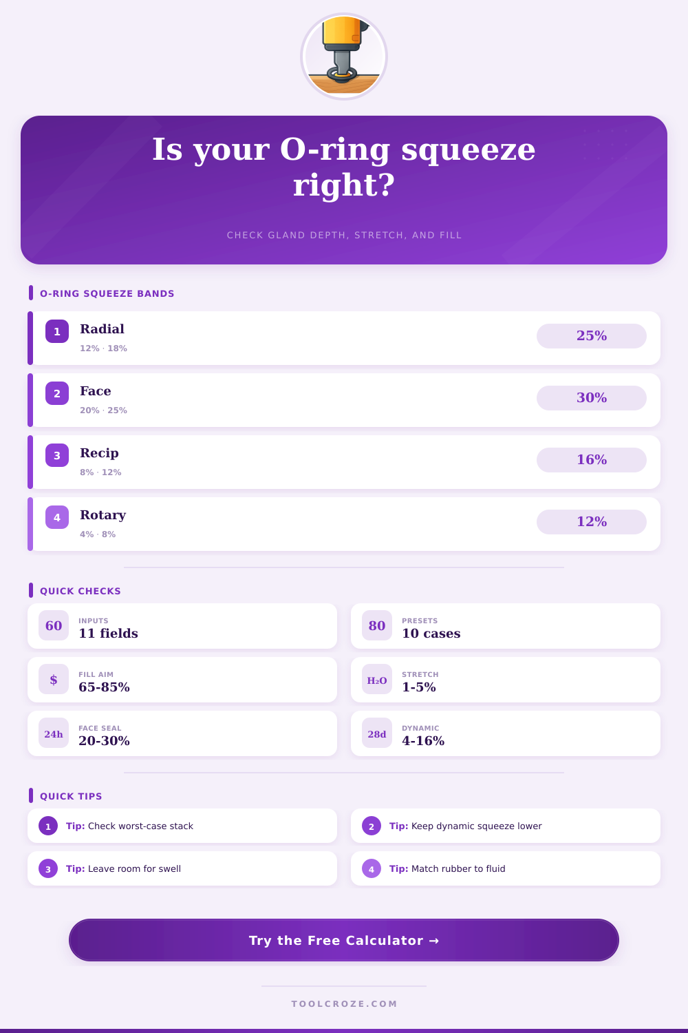
4Recommended Squeeze Bands
| Compression type | Typical squeeze | Usual target | Design notes |
|---|---|---|---|
| Static radial piston or rod | 12-25% | 16-20% | Good for bore and rod glands where friction is not cycling constantly. |
| Static axial face seal | 20-30% | 23-27% | Higher squeeze is common because friction is not a continuous sliding load. |
| Dynamic reciprocating | 8-16% | 10-13% | Lower squeeze reduces drag, heat, and wear while preserving contact. |
| Dynamic rotary | 4-12% | 6-9% | Use sparingly; rotary O-ring glands are sensitive to heat and lubrication. |
| Vacuum face seal | 25-35% | 28-32% | Higher squeeze helps leak rate but requires careful fill and closure force checks. |
These bands are practical screening ranges. Final values should be checked against the seal supplier gland chart, material, temperature, surface finish, and motion duty.
5Volume Fill Guide
| Volume fill | Interpretation | Where it fits | Action |
|---|---|---|---|
| Under 60% | Loose gland | Large grooves, low squeeze | Check extrusion, gland depth, and side loading. |
| 60-70% | Conservative fill | Dynamic or high swell fluids | Acceptable when squeeze and leakage checks are still met. |
| 70-85% | Preferred static range | Most face and radial seals | Good first-pass target with room for tolerance and swell. |
| 85-90% | Tight fill | Low swell, static only | Review swell, thermal expansion, and tolerance stack carefully. |
| Over 90% | Overfill risk | Usually avoid | Widen the groove or reduce squeeze before production release. |
6Pressure and Extrusion Notes
| Pressure class | Typical range | Gland concern | Common response |
|---|---|---|---|
| Low | Under 150 psi / 10 bar | Leakage and basic squeeze | Standard 70A material often works if compatibility is right. |
| Medium | 150-1500 psi / 10-100 bar | Extrusion gap and finish | Check clearance gap and consider harder compounds. |
| High | 1500-3000 psi / 100-200 bar | Gap extrusion | Use tighter glands, 80A-90A compounds, or backup rings. |
| Very high | Over 3000 psi / 200 bar | Rapid extrusion failure | Supplier review, backup rings, and pressure cycling validation are strongly advised. |
7Tolerance and Stretch Reference
| Check | Preferred range | Watch limit | Reason |
|---|---|---|---|
| ID stretch, static radial | 1-5% | Over 8% | Stretch reduces cross-section and can reduce squeeze below the drawing intent. |
| ID stretch, dynamic | 0-3% | Over 5% | Lower stretch helps friction, heat, and service life. |
| Face seal stretch | 0-2% | Over 4% | Face seals often rely on placement rather than high ID stretch. |
| Cross-section tolerance | Use spec limit | Never ignore | Small O-rings can swing squeeze dramatically from cord tolerance alone. |
| Depth tolerance stack | Machined tightly | Review at extremes | Worst shallow depth drives over-squeeze; worst deep depth drives leakage. |
8Shop Tips
O-ring squeeze is a critical variable that determines if an O-ring will last or if an O-ring will leak. Too much compression on a dynamic shaft will cook the O-ring in a few weeks of operation. Too little compression on a vacuum face seal will allow the atmosphere to entering the system at cold starts.
The interaction of gland depth, cord tolerance and stretch determines the outcome of an O-ring seal before the component ever hits a test bench. You have to use a dedicated calculation step to account for the interaction of these three variables. The tool will do the arithmetic for you when you input the correct dimensions for your gland and O-ring.
How to Check O-ring Squeeze and Fit
The tool will show you the nominal squeeze, worst-case squeeze based on tolerance stack, groove volume fill and the percentage of stretch in your system. By running these numbers, you will avoid the situation where you discover after purchasing the O-ring that the groove was overfilled. The inputs for the calculation include the type of compression that you are using in your system.
The type of compression will determine which squeeze band you use in your calculation. A face seal will allow for more compression than a low-speed rotary sealing application. The next input is the pressure class for your system.
Higher pressure class will allow for less extrusion of the O-ring and may require a different compound than one used at lower pressure classes. You must also input the cross-section tolerance and the gland depth tolerance for your application. These two parameters will determine if your nominal dimension will fall into a dangerous squeeze range when combined with each of the tolerance extremes.
Finally, you must also provide for a swell allowance in your O-ring for exposure to fuel, oil and heat. The outputs of the calculation will show you the nominal squeeze, the squeeze at the worst-case combination of tolerances, the volume fill of the groove and the stretch percentage of your O-ring. These outputs can be used to determine if your seal design is appropriate prior to sending your drawings to the shop for fabrication.
This calculator will discover three thing as they relate to sealing problems: the first problem is treating the nominal squeeze number as the only number that matters for your O-ring. The second is ignoring how the material will swell when in contact with the fluid in your system. The third is the assumption that a gland dimension sized from a handbook will survive the tolerance of the manufactured components.
The calculator will surface all three of these problems so that a design can be adjusted before any metal is cut from a billet. The third of the major factor that must be considered is the material of the O-ring. A 70-durometer NBR is used in general hydraulic systems.
A 70-durometer NBR will swell in certain types of ester-based fluids. FKM material will hold up more better to high heat and fuel exposure but becomes brittle in very cold temperatures. EPDM will handle steam and brake fluid but will fail if exposed to petroleum-based fluids.
Silicone will provide a low closing force for applications with delicate components but will tear more easy during installation. The material must be chosen based on the fluid type, temperature range and whether it will be exposed to motion. Durometer is another factor.
A 90-durometer compound has better resistance to extrusion but requires more closing force to seat the O-ring properly. Stretch is another factor to consider in the sealing application. A modest amount of stretch will allow the O-ring to seat properly in the groove during assembly.
A modest amount of stretch also allows for ID tolerance in the component to be sealed. Too much stretch, however, creates a thin O-ring that will not achieve the squeeze that was targeted during the design phase. Dynamic sealing application are very sensitive to stretch.
Face seals, on the other hand, work best with a near-zero stretch rate. The stretch percentage will help you to determine whether or not there needs to be a change to the O-ring size or the installed diameter of the component. Volume fill and squeeze have the same logic with the exception of groove fill takes into account the swelling of the O-ring to provide a dimension that will ensure that the groove will not be too deep for the O-ring.
A groove fill that is 60% full may seem okay but the material may roll out of the groove under low system pressure. A groove fill that is over 85% full will leave little margin for error for thermal expansion and swelling. For static seals, the preferred groove fill is somewhere between 70% and 85%.
For dynamic application a lower volume fill is needed to reduce friction between moving parts. Vacuum face seals, however, require a higher volume fill to reduce the number of leak paths. The volume fill that is provided will include the swell allowance that was input into the calculation.
The pressure class for the system plays a role in the squeeze calculation for the O-ring as well as in the squeeze target. For low pressure applications it is possible to use high squeeze percentage to ensure that the O-ring will establish a reliable seal between dynamic components. For medium pressure systems there is a risk of extrusion of the O-ring and harder compound seals or smaller gland tolerances may be required.
For high and very-high pressure systems it is common to require backup ring for the O-ring to prevent the O-ring from being destroyed in a few minutes. A warning will be provided in the output that indicates if the pressure class requires these types of modification. Tolerance stack is something that is often ignored in many drawings.
If the gland is too shallow or the O-ring is too large it will reduce the squeeze that is available for the O-ring to establish a seal. If the gland is too deep or the O-ring too small it could reduce the squeeze to a level below the minimum squeeze required for the application. The calculation will provide these two extremes as an output so that you can determine whether your design will survive the manufacturing tolerance.
By using the worst-case tolerance combination you can prevent failures of the prototype seal. For any new gland dimension you should run the calculation twice. The first calculation should use the nominal dimensions and a squeeze value that is the midpoint of the recommended squeeze band.
The second pass of the calculation should use the worst-case combination of tolerances to ensure that the design will survive tolerance stack during manufacturing of the component. You will apply the same logic to both metric and inch dimensioned component. A gland that works well with a set of dimensions may fall outside of the squeeze band requirement if the components are manufactured in metric units.
By calculating squeeze for both inch and metric units prior to ordering the O-rings you will avoid the common discovery that a 3.53 mm cross-section O-ring will not provide the squeeze required for proper operation once machined to tolerances. The toggle switch between inch and metric units will help with this decision. There are a few factor that the calculation cannot account for.
The surface finish of the components where the O-ring will be seated will affect the sealing action. Lubrication will affect friction and heat build-up in dynamic sealing applications. Method of installation may lead to nicking or twisting of the O-ring during installation.
Temperature will have an effect on both the elastomer and metal components. These factors are outside the calculation but the calculation is still necessary to provide an understanding of what can go wrong beyond the parameters of a calculation. In reviewing this calculation it is important to remember a few things.
First, the squeeze variable is a range not a single number. Second, the squeeze must be accounted for in the manufacturing of the component prior to manufacturing of the O-ring. Third, the elastomer must be chosen based on the type of fluid that will be used and the type of motion that the seal will experience.
Finally, an engineer must understand numbers from the calculation prior to the manufacturing of any metal part or the expenditure of any money.