🔧 O Ring Friction Calculator
Estimate O-ring running drag, breakaway force, pressure-assisted normal load, seal torque, and heat from squeeze, seal diameter, friction coefficient, lubricant factor, speed, contact width, and breakaway factor.
📌 Presets
⚙ Calculator Setup
🧪 Elastomer / Lube / Spec Grid
📐 Formulas Used
- Contact circumference = pi x seal diameter.
- Contact area = circumference x contact width.
- Squeeze stress = material base stress x (squeeze / 10)^1.25 x gland factor.
- Normal load = squeeze stress x contact area + pressure load x contact area x pressure factor.
- Effective coefficient = coefficient of friction x lubricant factor x material drag x surface factor.
- Running friction = normal load x effective coefficient x speed multiplier.
- Breakaway force = running friction x breakaway factor.
- Friction torque = running friction x seal diameter / 2.
- Heat rate = running friction x dynamic speed converted from lbf-in/s to watts.
📊 Reference Tables
| Material | Typical mu | Base stress at 10% squeeze | Use note |
|---|---|---|---|
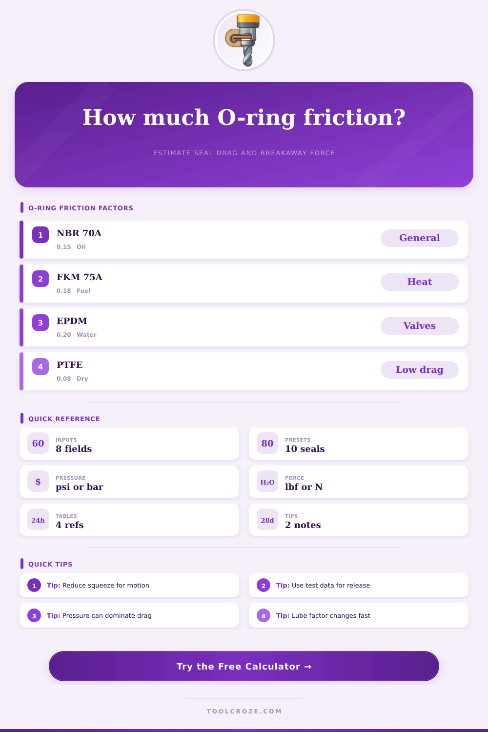
| NBR 70A | 0.12 to 0.20 | 120 psi | Good baseline for oil-wet rod and piston seals. |
| FKM 75A | 0.15 to 0.25 | 145 psi | Higher drag estimate for fuel, heat, and chemical service. |
| EPDM 70A | 0.16 to 0.28 | 110 psi | Use for water service after fluid compatibility review. |
| Silicone 70A | 0.18 to 0.35 | 95 psi | Soft material with sticky breakaway after dwell. |
| HNBR 80A | 0.14 to 0.24 | 170 psi | Higher contact stress in pressure-loaded dynamic seals. |
| PTFE encapsulated | 0.05 to 0.12 | 85 psi | Low sliding friction but less elastic conformance. |
| Lubrication | Factor range | Typical input | Design note |
|---|---|---|---|
| Assembly grease | 0.55 to 0.75 | 0.65 | Useful for installation and early cycling. |
| Oil wet | 0.45 to 0.70 | 0.55 | Often the lowest running drag for elastomer seals. |
| Water wet | 0.70 to 1.00 | 0.85 | Higher friction than oil in many compounds. |
| Dry surface | 1.00 to 1.35 | 1.20 | Expect higher breakaway and more heat. |
| PTFE film | 0.35 to 0.60 | 0.45 | Confirm compatibility with elastomer and fluid. |
| Gland / motion | Pressure factor | Speed factor | Typical squeeze |
|---|---|---|---|
| Rod reciprocating | 0.55 | 0.012 per in/s | 8% to 18% |
| Piston reciprocating | 0.70 | 0.010 per in/s | 10% to 20% |
| Slow rotary shaft | 0.35 | 0.018 per in/s | 5% to 12% |
| Static breakaway | 0.80 | 0.000 per in/s | 15% to 30% |
| Sliding face seal | 0.60 | 0.014 per in/s | 12% to 25% |
| Output | Formula cue | Watch point | Adjustment lever |
|---|---|---|---|
| Running force | N x mu effective | Actuator sizing | Lower squeeze or improve lube |
| Breakaway | Running x factor | Start motion | Reduce dwell, polish surface |
| Normal load | Squeeze + pressure | Pressure dominance | Check contact width estimate |
| Heat rate | Force x speed | Dynamic wear | Lower speed or improve film |
| Torque | Force x radius | Rotary seals | Reduce seal diameter or drag |
💡 Tips
This calculator estimates O-ring friction from squeeze, pressure, diameter, contact width, lubricant condition, speed, and breakaway. Compare results with test data before final actuator sizing.
O-ring friction is a force that can cause a cylinder to stick or a rotary shaft to run warm. The problem with O-ring friction is that there is no set number for O-ring friction. O-ring friction vary with several factors.
O-ring friction varies with squeeze percentage, fluid pressure, lubrication, material choice, surface finish, breakaway force, and heat created at the point of contact. The squeeze percentage are one of the inputs into the equation for calculating O-ring friction. A squeeze percentage that is too low can cause the O-ring to leak.
What Makes O-Ring Friction and How to Reduce It
A squeeze percentage that is too high will force the rubber to press harder than it need to against the mating surface component. High squeeze percentages will create high drags for the moving component and high amount of heat within the O-ring. The diameter and the contact width of the O-ring will have an impact on the friction created by the O-ring.
The diameter and contact width will determine the force created from the squeeze. The larger the contact width, the more force that will be applied to the component. Fluid pressure will also have an impact on the friction created by the O-ring since the fluid will contribute to the normal load on the O-ring.
A calculator can help to set each of these variables so that the user dont have to guess at the influence of the fluid pressure on friction. Additional factors that will impact the friction created by the O-ring are the lubrication and materials used for the O-ring and its mating component. The coefficient of friction for the materials is only a starting point to estimate the friction created by the O-ring.
Using a thin film of oil can reduce the coefficient of friction by half. The coefficient of friction will be higher for a dry mating surface. These factor have to be accounted for when calculating O-ring friction.
The surface finish will also impact the coefficient of friction for the O-ring. Using a polished rod can lower the coefficient of friction compared to a rough surface. While these adjustments may be small, small adjustments to the surface finish will help to maintain the force provided by the actuator within the limits of the system and avoid premature wear of the components.
Breakaway force is another factor that can impact the friction created by the O-ring and which many people dont account for. After sitting in place under a load for some period, the rubber portion of the O-ring may have bonded to the mating surface. Or, the rubber may conform to the texture of that mating surface.
Thus, more force will be required to initiate movement compared with the force required to maintain that movement. Using a breakaway force multiplier will allow users to test different breakaway times and different surface conditions. A breakaway factor of 1.6 is commonly used when the O-ring has been sitting in one position for short period of time.
For longer periods of time or higher fluid pressure, the breakaway force may have to be set at 2.0 or higher. Since breakaway force is often higher than the running friction created by the O-ring, breakaway force is a very important variable to consider when sizing an actuator. The last factor to consider is the heat created by the O-ring.
Even modest amount of drag at a moderate speed will generate heat at the point of contact between the O-ring and its mating component. This heat can impact the O-rings rubber components. The heat will soften the rubber and possibly impact the lubricant film that sits between the two mating components.
Since heat can shorten the life of the O-ring, it is important to be able to calculate the rate of heat that is created by the O-ring using a calculator that estimates O-ring friction. Using the information from this calculation will allow users to determine if additional cooling is required for the system or if a different lubricant is required. The biggest mistake that many people make is treating O-ring friction as a single variable and setting it to a number.
Using such a number will result in incorrect sizing of the actuator that will create premature wear of the components. For instance, using a squeeze percentage of 15 percent may have worked with the actuator on a previous job. However, the diameter of that previous actuator may have been different than the one that is to be used on the new job.
Thus, the friction created at 15 percent squeeze will not necessarily be the same on the new actuator. Additionally, using an actuator with a low coefficient of friction may be selected for minimizing the friction created. However, if the lubricant for that system is likely to break down at the heat that is generated at the O-ring, that may lead to premature wear of the O-ring.
Reference tables can help to avoid such mistakes. In addition to the factors discussed above, there are also complications to O-ring friction in real-world applications. For instance, temperature swings can impact the stiffness of the rubber and the viscosity of the lubricant.
Additionally, the fluid used to lubricate the O-ring may react with the rubber in a way that reduces its effectiveness as a lubricant. Finally, manufacturing tolerances may impact the squeeze that is applied to the O-ring. Thus, the only true way to determine the friction created by an O-ring in a specific application is to measure it on a prototype of that actuator.
While a calculator will help to compare the impact of various choices of variables on the friction created by the O-ring, it cant account for these complications. Thus, one of the first calculations that should of been performed is the estimation of the friction created by the O-ring. Since several of the input variables for the calculation can be adjusted, this initial calculation will allow the designer to make adjustments to the actuator design that will reduce the friction created by the O-ring.
For example, reducing the squeeze percentage will likely cost less than purchasing an actuator that uses an O-ring with a more premium low coefficient of friction. Additionally, improving the surface finish of the rod is a much cheaperer option than increasing the size of the actuator. O-ring friction is the result of several decisions that were made when actuator components were selected.
Thus, the same variables that determine the performance of the O-ring also determine the friction and heat that is created. Thus, before purchasing the actuators and their components, the numbers should be run to ensure that the design of the actuator will remain within the limits that were set for its operation.