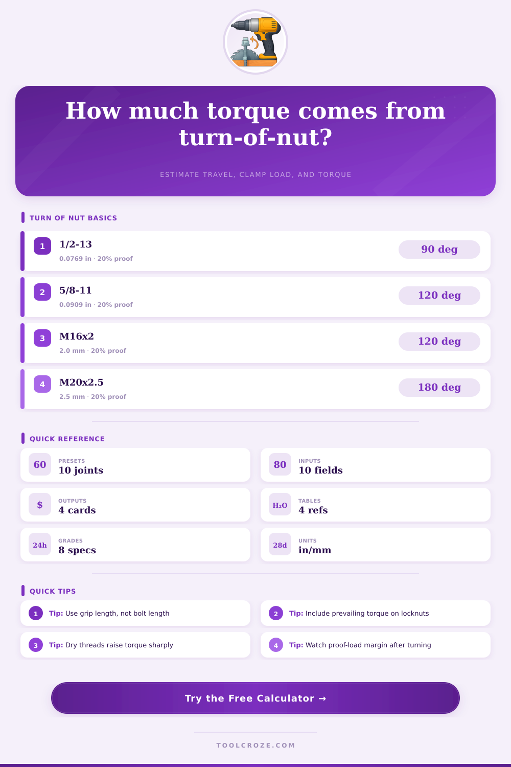
🔩 Turn of Nut Torque Calculator
Estimate thread advance, bolt stretch share, final clamp load, and torque from the turn-of-nut method for steel, machinery, and structural bolted joints.
📌 Preset Bolted Joints
⚙ Joint Inputs
🎯 Results
📈 Bolt Grade Comparison Grid
📊 Reference Tables
| Grip Condition | Approx Grip / Dia | Typical Turn | Use Note |
|---|---|---|---|
| Short hardened joint | 3d or less | 60 to 90 deg | Rigid plates, short elastic length, fast load rise |
| Medium steel stack | 3d to 6d | 90 to 120 deg | Typical structural splice or machine frame |
| Long structural stack | 6d to 10d | 120 to 180 deg | Large grip allows more turn before proof margin is reached |
| Soft or gasketed layer | variable | 180 to 240 deg | Compression losses require verification after seating |
| Lubrication State | Nut Factor K | Torque Effect | Comment |
|---|---|---|---|
| Waxed or moly paste | 0.12 | Lowest torque | High preload repeatability when controlled carefully |
| Light oil / zinc flake | 0.15 | Low torque | Common for coated high-strength bolting |
| Plain oiled steel | 0.18 | Baseline torque | Useful default when actual testing is not available |
| Dry or galvanized dry | 0.21 to 0.24 | Higher torque | Friction dominates the torque increase very quickly |
| Bolt Grade | Proof Stress | Suggested Snug | Typical Use |
|---|---|---|---|
| A325 / Grade 5 | 85 ksi | 15 to 20% | Structural splice plates, equipment frames |
| A490 / Grade 8 | 120 ksi | 15 to 20% | High-strength compact joints and heavy flanges |
| Class 8.8 | 600 MPa | 18 to 22% | Base plates and structural machinery bolting |
| Class 10.9 / 12.9 | 830 to 970 MPa | 15 to 20% | Rail clips, tooling, and wind-brace hardware |
| Common Thread | Lead Per Turn | Tensile Area | Quick Note |
|---|---|---|---|
| 1/2-13 UNC | 0.0769 in | 0.1419 in2 | Common machinery and light structural size |
| 3/4-10 UNC | 0.1000 in | 0.3345 in2 | Good example of 120 degree turn loading |
| M16 x 2.0 | 2.0 mm | 156.7 mm2 | General metric steel support bolt |
| M20 x 2.5 | 2.5 mm | 244.8 mm2 | Heavy bracket and rail restraint size |
💡 Practical Notes
This calculator estimates turn-induced preload from thread lead, bolt stiffness, and joint compression. Use it to compare clamp load and torque across structural steel, machinery, and metric bolted joints.
The turn-of-nut method is a way to tighten bolt by rotating the nut after it reaches a snug position by a specific number of degrees. The turn-of-nut method is used because the method provide preload to the bolt without the use of expensive torque wrenches. In order to use the turn-of-nut method, the bolt must first be snugged.
In order to achieve this condition, the bolt must initially be finger-tight and then further tightened with a wrench until the bolt is seated into the joint. After the bolt is snugged, a prescribed angle rotates the bolt further. The angle through which the nut should be rotated depend upon the length of the grip on which the bolt is installed, and the stiffness of the joint to which the bolt is being installed.
How to use the turn-of-nut method to tighten bolts
The length of the grip on which the bolt is installed is one of the critical factors in the turn-of-nut method. Grip length is the distance from the underside of the bolt head to the face of the nut. Grip length is not the same as the length of the bolt.
Short grips allow for the joint to be very stiffly, as the bolt will stretch quickly when the nut is rotated. Long grips allow for the joint to be less stiff. A longer grip means that the joint will compress more when the bolt is tightened.
Therefore, it is important to be able to determine the length of the grip on which the bolt is installed. Another factor that affects how much the nut will turn on the bolt is the friction between the two components. Friction is expressed in the nut factor, which is also labeled as an K factor.
The K factor will change according to whether the threads on the bolt are dry, oiled, or are being lubricated with a specialized paste. For instance, dry threads will have a high K factor, as will galvanized threads. However, the K factor will be lower for bolts whose threads is lubricated.
Since the K factor will change according to the lubrication of the threads, it is important to use the same K factor for the joint being assembled. If the lubrication changes during assembly, the K factor will change, which may prevent the bolt from achieving the desired clamp load. The specifications of the bolt will also determine the limits of the turn-of-nut method.
Every bolt has a proof load, which is the maximum amount of tension that the bolt can be tightened to without permanently deforming the bolt. The tension that is applied during the turn-of-nut method must not exceed the proof load of the bolt. For instance, A325 structural bolts have specific proof loads, as do A490 structural bolts, but the proof loads for each of these bolts are different.
Additionally, the pitch of the threads will play a major role in how much the bolt advance when the bolt is tightened with the nut. Coarse threads will move the nut further along the bolt than fine threads. The concept of the turn-of-nut method relies upon the concept that when the nut is rotated, the nut will move along the threads of the bolt.
This movement will stretch the bolt, and create the tension that will create the preload of the joint. Preload is the clamp load that is placed into the joint with the bolt in order to prevent the joint from loosening or leaking. Thus, the turn-of-nut method is a way to manage the tension that rotating the nut places into the bolt.
In order to successfully use the turn-of-nut method, it is important to avoid some mistake that are common when using this method. For instance, it is easy to over-snug the bolt before beginning to rotate the nut. Over-snugging the bolt will make the nut too stiff to rotate.
Another common mistake is to ignore the prevailing torque of a locknut. If the prevailing torque is not considered, the total torque that will be applied to the bolt will not be achieved. Finally, it is important to remember that gaskets will absorb some of the clamp load that is created when the bolt is tightened.
Thus, in a gasketed bolt joint the preload will have to be determined in another way. If the grip length, the nut factor, and the prevailing torque can be accurately determined for a joint, the mathematics of the turn-of-nut method will provide a way to calculate the rotation of the nut that will achieve the necessary clamp load.