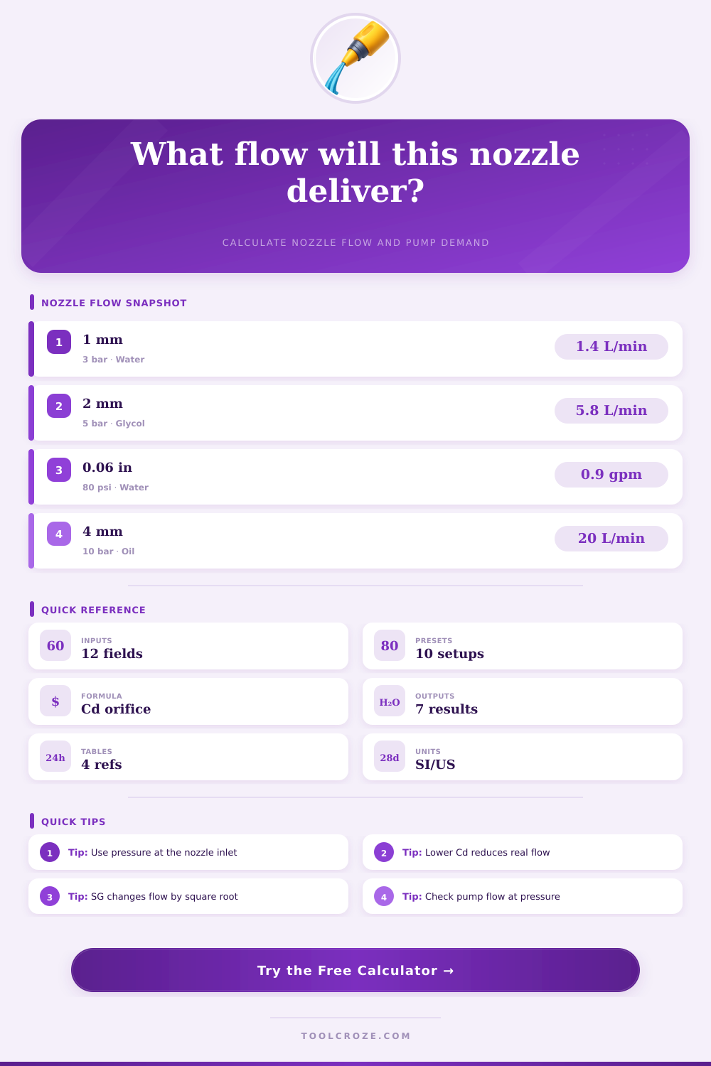
Nozzle Flow Rate Calculator
Estimate real nozzle discharge from orifice diameter, pressure drop, discharge coefficient, specific gravity, nozzle count, spray angle, and target pump flow.
Choose a starting point for industrial washdown, misting, cooling, tank cleaning, irrigation, dosing, and hydraulic jet applications.
Nozzle Flow Results
| Nozzle or Opening | Typical Cd | Use Case | Calculation Note |
|---|---|---|---|
| Sharp-edged drilled orifice | 0.60 to 0.64 | Restrictors, metering plates | Strong vena contracta, lower real flow |
| Rounded entrance nozzle | 0.78 to 0.86 | Smooth water jets, test benches | Less contraction, higher real flow |
| Full cone hydraulic insert | 0.68 to 0.80 | Rinsing, dust control, tank spray | Internal vane loss lowers Cd slightly |
| Flat fan hydraulic slot | 0.64 to 0.76 | Wash bars, cooling, cleaning lines | Pattern slot affects flow coefficient |
| Fine mist impingement insert | 0.45 to 0.60 | Humidification, evaporative cooling | Small passages add friction and clog risk |
| Venturi aspirating nozzle | 0.38 to 0.55 | Foam, aeration, chemical induction | Air or suction port changes flow behavior |
| Orifice Diameter | 3 bar / 44 psi | 5 bar / 73 psi | 10 bar / 145 psi |
|---|---|---|---|
| 1.0 mm / 0.039 in | 0.81 L/min / 0.21 gpm | 1.04 L/min / 0.28 gpm | 1.48 L/min / 0.39 gpm |
| 1.5 mm / 0.059 in | 1.82 L/min / 0.48 gpm | 2.35 L/min / 0.62 gpm | 3.32 L/min / 0.88 gpm |
| 2.0 mm / 0.079 in | 3.23 L/min / 0.85 gpm | 4.17 L/min / 1.10 gpm | 5.90 L/min / 1.56 gpm |
| 3.0 mm / 0.118 in | 7.27 L/min / 1.92 gpm | 9.39 L/min / 2.48 gpm | 13.28 L/min / 3.51 gpm |
| 4.0 mm / 0.157 in | 12.93 L/min / 3.42 gpm | 16.69 L/min / 4.41 gpm | 23.60 L/min / 6.24 gpm |
| Fluid | Typical SG | Flow Multiplier vs Water | Design Note |
|---|---|---|---|
| Clean water | 1.00 | 1.00 | Baseline for most nozzle charts |
| 30% glycol-water | 1.04 | 0.98 | Confirm viscosity at low temperature |
| Salt brine | 1.18 | 0.92 | Use corrosion-resistant nozzle material |
| ISO 32 light oil | 0.86 | 1.08 | Viscosity can reduce actual Cd |
| Liquid fertilizer | 1.25 | 0.89 | Flush solids and check strainer size |
| Spray Angle | Width at 0.3 m | Width at 0.6 m | Width at 1.0 m |
|---|---|---|---|
| 15° | 0.08 m / 3.1 in | 0.16 m / 6.3 in | 0.26 m / 10.5 in |
| 40° | 0.22 m / 8.6 in | 0.44 m / 17.2 in | 0.73 m / 28.6 in |
| 65° | 0.38 m / 15.1 in | 0.76 m / 30.1 in | 1.27 m / 50.2 in |
| 110° | 0.86 m / 33.8 in | 1.71 m / 67.6 in | 2.86 m / 112.6 in |
| Nozzle Style | Typical Material | Fluid Fit | Best Calculation Use |
|---|---|---|---|
| Solid stream jet | Stainless or ceramic | Water, oil, coolant | Velocity, reaction force, target impact |
| Full cone hydraulic | Stainless, brass, acetal | Rinse water, detergent, brine | Header flow and pump pressure checks |
| Fine mist insert | Stainless, ruby, ceramic | Filtered water, glycol mix | Small-orifice flow with conservative Cd |
| Venturi foam nozzle | Polymer or stainless | Detergent, air-liquid mix | Liquid feed estimate before aspiration |
| Rotary tank washer | 316 stainless | Water, caustic, process rinse | Total pump flow across several jets |
Nozzle flow is an critical factor in that the accuracy of the nozzle flow will determine whether the system will perform its function properly. If the nozzle flow are incorrect, the system may waste fluids, or the system might not be able to achieve it’s desired function. Many people considers a nozzle to be a simple hole in an object.
However, the pressure at the inlet of the nozzle, the weight of the fluid, and the resistance of the nozzle opening against the fluid discharge influence the flow of fluid through a nozzle. If these factors isnt accounted for in the function of the system, the fluid will not hit the target. Another critical factor that will influence the fluid system is the discharge coefficient.
Main Things That Affect Nozzle Flow
The discharge coefficient accounts for the sharpness of the edges of a nozzle opening, any internal vanes that may be inside the nozzle, and the contraction of the fluid that occurs at the exit of the nozzle bore. For instance, a nozzle that has a sharp orifice may have a discharge coefficient of 0.62, but the same nozzle with a rounded entrance may have a discharge coefficient of 0.82. These coefficients help to determine how much fluid will be forced through the nozzle at a given pressure.
A calculator can help to determine the impact of altering the nozzle geometry by allowing the user to select a nozzle profile or to enter a custom value of the nozzle discharge coefficient. Specific gravity is another important factor to consider when designing a fluid system. The specific gravity of a fluid will impact the amount of resistance that the fluid will present against being accelerated by the system.
For instance, a fluid that is heavy such as salt brine with a specific gravity of 1.18 will move at a higher rate then a fluid with a specific gravity of 1.0 such as water at the same pressure. The specific gravity can be changed from one type of fluid to another such as using a rinse header fluid to a chemical line fluid, or from water to a winter blend fluid. A tool that allows for the selection of fluids or the entry of a custom value of the fluids specific gravity can change the specific gravity of a fluid.
Many fluid system designs fail to account for one factor that can introduce errors into the systems performance: the location of the pressure measurement. For instance, the pressure at the pump may be ten or fifteen percent higher than the pressure that the fluid will reach at the nozzle. The friction of the fluid moving through hoses, elbows, and strainers in the system causes such losses in pressure.
Such pressure loss can be accounted for with a loss allowance field in the calculator. By including this field, an estimate of the pressure that the pump must create will provide an accurate reading of the systems requirements. The velocity and reaction force of the fluid exiting the nozzle are two factors that relate to the safety of the system.
High velocities of fluid will create a reaction force that may push on the lance or manifold. This reaction force can be viewed in the same calculation as the flow rate of the fluid; knowing this reaction force will allow the designer to decide whether additional bracing is required to support the reaction force of the fluid ejection. Spray angle and distance are two factors that relate to the coverage of the fluid from the nozzle.
By using a footprint calculation, the spray angle of the nozzle and the distance from the nozzle to the target can help to determine the width of the spray of fluid. This measurement will help the designer to determine whether the system will reach the edges of the target. Many factors may complicate the use of real fluids in a nozzle system.
For instance, the viscosity of the fluid changes with the fluids temperature. Some fluids that contain multiple liquids will thin out as they travel through the small orifice of the nozzle. Additionally, solids that are contained within the fluid will erode the nozzle over time, increasing the discharge coefficient and the flow rate of fluid.
A reference table of typical values for nozzles can help the designer to start with a realistic number for the discharge coefficient or specific gravity of the fluid. To determine the parameters of a fluid system that includes nozzles, it is important to treat the nozzle as only one component of the system. The fluid system will have a pressure that must be measured at the location of the nozzle, the designer will have to select the discharge coefficient based off the nozzle that was purchased, and the properties of the fluid will have to be accounted for.
By considering each of these factors, the other components of the system, including the size of the pump, the size of the hoses, and the amount of the target that will be covered by the spray from the nozzles, will becomes easier to determine.