Miter Cut Pipe Angle Calculator
Calculate pipe miter cut angle, segment length, centerline radius, long-to-short offset, kerf allowance, fit-up gap, and layout clock marks for fabricated pipe elbows.
⚙Real Pipe Miter Presets
Pick a common shop layout, then adjust pipe outside diameter, bend angle, joint count, radius, kerf, and gap for your actual fit-up.
📏Pipe and Bend Inputs
Calculated Miter Layout
🧱Selected Pipe and Spec Grid
📊Common Bend and Cut Angle Reference
| Total Bend | Miter Joints | Joint Deflection | Cut Angle | Typical Use |
|---|---|---|---|---|
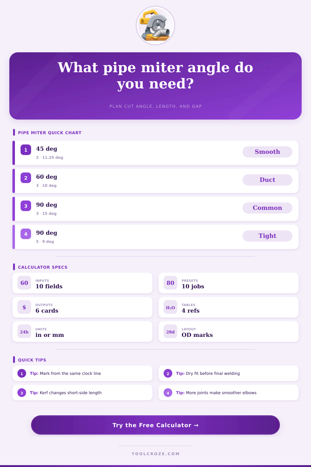
| 22.5° | 1 | 22.5° | 11.25° | Single shop offset or trim turn. |
| 45° | 2 | 22.5° | 11.25° | Smoother two-joint fabricated elbow. |
| 60° | 3 | 20° | 10° | Duct and tube transitions. |
| 90° | 3 | 30° | 15° | Common three-joint pipe elbow. |
| 90° | 5 | 18° | 9° | Smoother large diameter elbow. |
🔧Pipe OD and Wall Reference
| Nominal Size | OD | Sch 40 Wall | ID Estimate | Layout Note |
|---|---|---|---|---|
| NPS 1 | 1.315 in | 0.133 in | 1.049 in | Good for handrail and small process pipe. |
| NPS 2 | 2.375 in | 0.154 in | 2.067 in | Mark carefully because small OD magnifies errors. |
| NPS 4 | 4.500 in | 0.237 in | 4.026 in | Common shop size for fabricated elbows. |
| NPS 6 | 6.625 in | 0.280 in | 6.065 in | Use more joints for smoother flow and fit-up. |
| NPS 8 | 8.625 in | 0.322 in | 7.981 in | Check wrap template stretch and seam alignment. |
| DN100 | 114.3 mm | 6.0 mm | 102.3 mm | Metric equivalent used in many fabrication shops. |
📐Clock Mark Layout Multipliers
| Clock Position | Circumference Fraction | Axial Shift Formula | Example Use | Marking Note |
|---|---|---|---|---|
| 12 o'clock | 0% | +0.5 x OD x tan(cut) | Long side peak | Use as the reference high point. |
| 3 o'clock | 25% | 0 | Side neutral | Cut line crosses center length. |
| 6 o'clock | 50% | -0.5 x OD x tan(cut) | Short side valley | Check kerf and root gap here. |
| 9 o'clock | 75% | 0 | Side neutral | Opposite side center crossing. |
⚒Kerf and Fit-Up Planning Reference
| Cut Method | Typical Kerf | Gap Range | Best Use | Practical Check |
|---|---|---|---|---|
| Cold saw | 0.06 to 0.10 in | 1/16 in | Accurate small and medium pipe cuts. | Blade thickness is usually consistent. |
| Abrasive chop saw | 0.09 to 0.14 in | 1/16 to 1/8 in | General steel fabrication. | Wheel wear can widen the kerf. |
| Band saw | 0.035 to 0.063 in | 1/32 to 1/16 in | Controlled shop cutting. | Check drift before cutting all pieces. |
| Plasma | 0.08 to 0.16 in | 1/16 to 1/8 in | Large pipe and plate templates. | Remove bevel and dross before fit-up. |
| Oxy-fuel | 0.10 to 0.20 in | 1/8 in | Heavy wall field work. | Grind the face to the final line. |
Ever work in a shop and get nervous? Ever lay out forty-five degree piece of pipe and look at it and try to figure out how many three miter do I need to make a ninety degrees turn? Even if you think you laid out correctly on paper, sometimes that just doesn’t feel right to your brain.
This does all the math for you, so you don’t go wrong until you start making your marks on the material. All you need to know is what you’re measuring.
How This Tool Helps You Cut Pipe
When cutting same 45 degree angle on both sides, most fabricators understands this doesn’t yield a smooth ninety degree corner; instead it results in a sharp cut which interrupt the flow and looks like an amateur job. Properly mitering the elbow require using several small cuts to mimic the curve.