MIG Welding Wire Speed and Voltage Calculator
Estimate practical MIG starting settings from wire diameter, material thickness, transfer mode, shielding gas, joint style, bead size, stickout, amperage target, WFS IPM, voltage range, travel speed, and deposition rate.
📌MIG Setup Presets
⚙Wire Speed and Voltage Inputs
MIG Wire Speed and Voltage Results
📊Calculated Setup Snapshot
🔧Wire and Gas Specification Grid
| Wire / Metal | Typical Gas | Common Transfer | Practical Setting Notes |
|---|---|---|---|
| ER70S-6 mild steel, 0.023 to 0.035 in | 75/25 argon CO2 or 100% CO2 | Short circuit | Good for sheet metal, auto panels, small brackets, and general shop welds. |
| ER70S-6 mild steel, 0.035 to 0.052 in | 90/10 argon CO2 or 98/2 argon oxygen | Spray or pulse | Needs enough amperage and argon-rich gas to avoid globular transfer. |
| ER308L / ER309L stainless, 0.030 to 0.045 in | Tri-mix or 98/2 argon oxygen | Short, spray, or pulse | Usually benefits from lower heat input and controlled travel speed. |
| ER4043 / ER5356 aluminum, 0.035 to 1/16 in | 100% argon or argon helium | Spray or pulse | Wire feed speed is high because aluminum wire is low density. |
| Silicon bronze ERCuSi-A, 0.030 to 0.035 in | 100% argon | Brazing / short arc | Use lower heat than steel fusion welding to limit base metal melting. |
⚡Starting Settings by Thickness
| Material Thickness | Steel Wire | Short Circuit Start | Travel Speed Range |
|---|---|---|---|
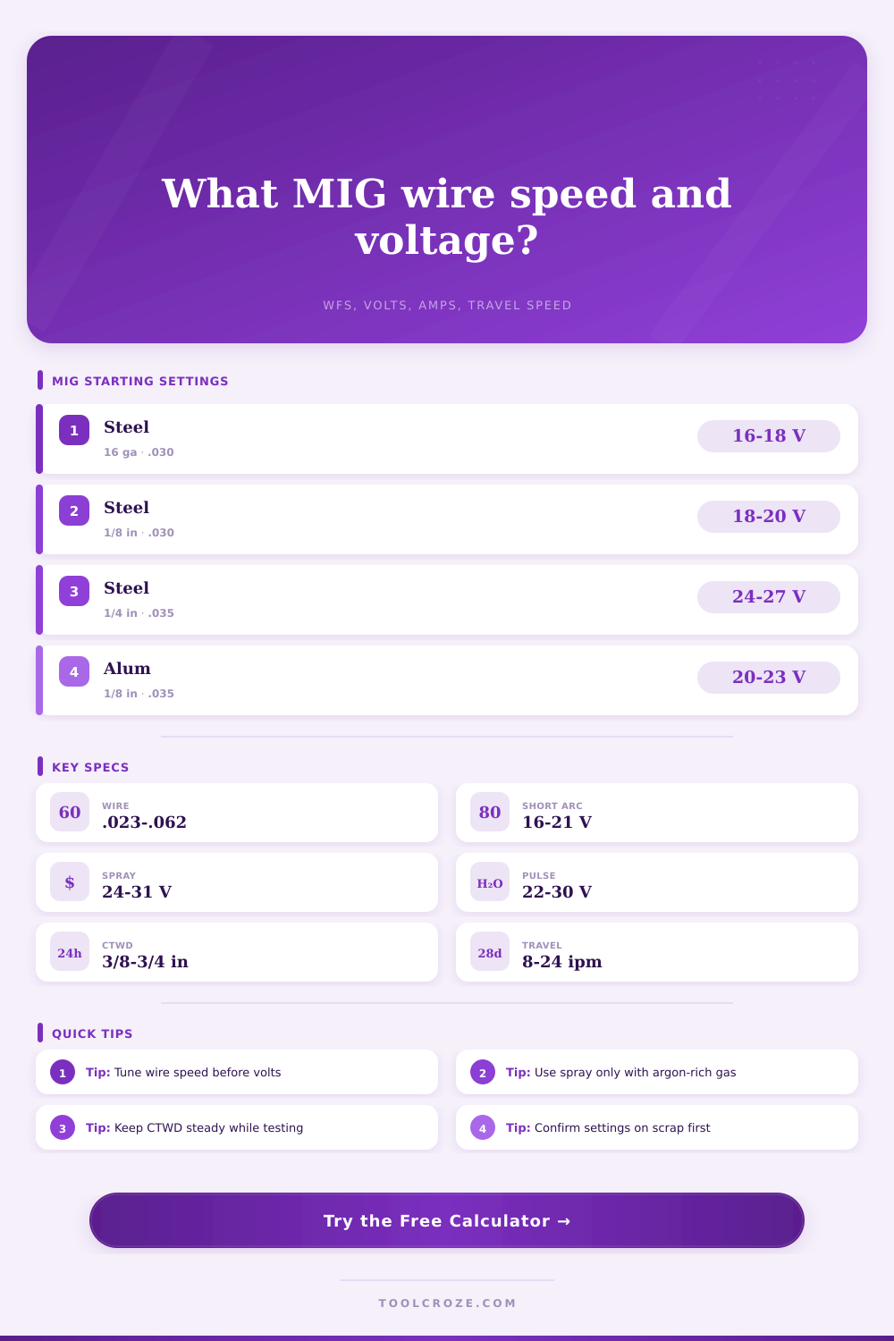
| 22 to 18 gauge, 0.030 to 0.048 in | 0.023 or 0.030 in | 35 to 70 A, 14 to 17 V, 120 to 230 IPM | 12 to 24 in/min with small stringer beads |
| 16 to 14 gauge, 0.060 to 0.075 in | 0.030 in | 70 to 95 A, 16 to 18.5 V, 170 to 260 IPM | 10 to 20 in/min for lap or butt joints |
| 1/8 in, 0.125 in | 0.030 or 0.035 in | 115 to 140 A, 18 to 20.5 V, 230 to 320 IPM | 8 to 16 in/min for fillet welds |
| 3/16 in, 0.188 in | 0.035 or 0.045 in | 150 to 190 A, 20 to 23 V, 240 to 360 IPM | 7 to 14 in/min; multipass may be cleaner |
| 1/4 in, 0.250 in | 0.035 or 0.045 in | 180 to 240 A, 23 to 28 V, 280 to 430 IPM | 6 to 12 in/min, spray or pulse when gas supports it |
🔀Transfer Mode Reference
| Transfer Mode | Typical Voltage | Typical Amperage | Best Use in the Calculator |
|---|---|---|---|
| Short circuit | 16 to 21 V | 40 to 180 A | Thin steel, out-of-position work, root passes, and low heat input. |
| Globular | 20 to 25 V | 160 to 260 A | Transition zone often used only when gas and machine limit spray. |
| Axial spray | 24 to 31 V | 180 to 350 A | Flat and horizontal welds on thicker steel with argon-rich gas. |
| Pulsed spray | 22 to 30 V | 80 to 320 A | Controlled heat on stainless, aluminum, and out-of-position work. |
| MIG brazing | 13 to 17 V | 40 to 120 A | Silicon bronze lap joints and thin coated sheet with lower heat. |
📝Tuning Response Table
| Observed Bead | Likely Setting Issue | Calculator Adjustment | Check Before Changing |
|---|---|---|---|
| Wire stubs into the puddle | WFS too high or volts too low | Lower WFS 5% or add 0.5 to 1.0 V | Keep stickout at the entered CTWD. |
| Arc sounds harsh and bead is flat | Voltage too high for WFS | Reduce voltage 0.5 to 1.5 V | Confirm gas flow and work clamp contact. |
| Cold toe or tall rope bead | Heat input or travel speed mismatch | Raise amps/WFS or slow travel slightly | Confirm joint fit-up and metal cleanliness. |
| Burn-through on thin sheet | Amps too high for thickness | Use cooler trim or smaller wire diameter | Check gaps, pulse spacing, and backing. |
| Excess spatter in spray range | Gas does not support spray transfer | Select short arc or argon-rich gas | Verify cylinder mix before increasing volts. |
💡MIG Calculation Tips
That’s when most problems on the shop floor begin: Spatter all over your shoes full of iron shavings. You pick up the gun, pull the trigger and what do you have? It is a violent sputter where there should of been a smooth bead. Time to turn up the voltage knob; that’s what it seems like anyway. But more often than not, voltage isn’t the culprit.
Most likely, it’s the balance between heat used to melt the wire and the speed at which wire is fed. You provide the wire diameter and material thickness and the rest is done by the calculator. You no longer have to guess with coefficients for deposit rate and amperage. It converts physical parameters such as shielding gas mix and base metal thickness into concrete settings for voltage and wire feed speed range. Then it calculates the amps required based off the metal thickness, and converts those amp requirements to inches per minute for a particular wire size.
How to Fix Welding Problems
Why does this matter? Because amperage is the real power behind the arc, it’s what makes it go! Wire speed just delivers that power. The tricky part comes in selecting proper transfer mode. For thin sheet metal, short circuit transfer, known as low heat input. Are the default setting. That’s because the arc will re-establish itself quickly after the weld pool breaks. This keeps the weld pool relatively cool, preventing thin sheet metal parts from melting. Standard shielding gas mixes (such as a 25-percent CO2/75-percent argon) operate this way. Another plus is that it operates quietly and is less picky about dirty metals. One minus: it tends to be spattery if the voltage is too low for wire speed. When out-of-whack, you’ll know…you’ll actualy hear it, like a sharp crackle.
This one needs way more argon in the mix of gases as well as more ampers to keep the arc stable. With spray transfer, the wire doesn’t drop big chunks of melted metal onto the workpiece. Instead, it sprays it across the arc, so there is very little or even no spatter and a much smoother bead. It is great when depositing lots of metal and working on flat surfaces on larger pieces of steel. The caveat here is you can’t do this setting on thin metal without burning right through the piece. The heat applied from spray transfer are just too great for thinner gauges. You must also have argon rich gas to help keep the arc stable in the transfer process. If not you’ll get into the globular zone which is inefficient and messy.
Aluminum conducts heat away from the arc much faster than steel, which require some special considerations. It also develops an oxide layer which is more difficult to melt with a higher melting point than the underlying metal. A mix of argon and helium or pure argon work best to break down this layer. Aluminum will appear to have a really fast wire feed speed on the calculator, mostly because the wire is physically larger and less dense than steel wire of the same diameter. Don’t be concerned by these large numbers; they does not show huge heat input. Amperage stays relatively low for thin aluminum sheets, so energy transfer is actually moderate.
Another factor that quietly sabotages welds is the contact tip to work distance. How far the stick out is also a factor and one that goes into the wire’s resistance. The wire’s electrical resistance start heating it up as soon as it leaves the tip, before it even hits the arc. That early heating will affect the feeding consistency and may even cause the wire to buckle. While you don’t have to get exactly the right number here, it’s more critical to maintain consistency with every weld. So if you vary the stickout just an 1/2-inch, you should adjust your voltage accordingly to account for resistance differences.
All of this is linked to your travel speed. The calculator estimates a reasonable travel speed based on the bead size you are targeting. Too fast, and you’ll end up with a narrow, ropey bead that wasn’t fused well at the toes. Too slow, and you risk either burning through the dough or adding so much reinforcement that you end up with something resembling a worm on top. You just need to find a beat at which the molten puddle flows smoothly in front of the arc. As long as you can watch the puddle close back over the arc as you continue forward, you’re good to go.
There’s no substitute for testing on scrap metal. There are too many variables, like the room temperature, a draft in the shop, or just how dirty my piece of work is. Nothing takes the place of experience, no matter how accurate calculations. Dial it in by cranking up the wire speed a bit if the arc is rough, and back off the voltage if the bead isn’t right. It’s a balancing act. When you get it dialed in, you’ll hear that smooth arc and know things are right. Your shoes will be clean, the bead will lay down evenly and there will be no more spatter.