MIG Shielding Gas Calculator
Estimate shielding gas demand from CFH flow, weld time, duty cycle, cylinder pressure, purge loss, waste, gas mix, travel length, and travel speed.
Gas use breakdown
| Gas mix | Typical CFH | Best fit | Calculator note |
|---|---|---|---|
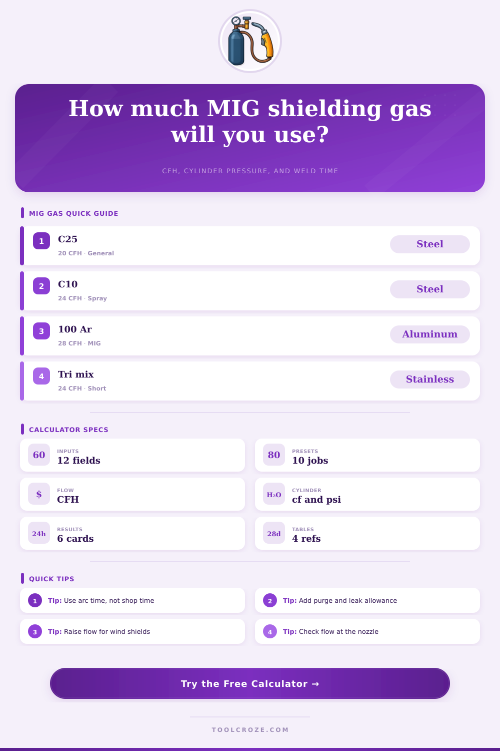
| C25, 75 percent argon / 25 percent CO2 | 18 to 25 | Short circuit mild steel | Stable all-purpose shop baseline |
| C20, 80 percent argon / 20 percent CO2 | 18 to 26 | Mild steel with cleaner bead profile | Slightly more argon than C25 |
| C10, 90 percent argon / 10 percent CO2 | 22 to 30 | Spray transfer on steel | Often needs higher voltage and steady flow |
| 100 percent argon | 25 to 35 | Aluminum MIG | Common spool gun and push-pull choice |
| Helium argon CO2 tri mix | 20 to 28 | Stainless short circuit | Use the mix your procedure specifies |
| 100 percent CO2 | 20 to 30 | Deeper steel penetration | More spatter and different arc feel |
| Cylinder rating | Approx full gas | Minutes at 20 CFH | Shop use |
|---|---|---|---|
| 20 CF MC | 20 cubic feet | 60 minutes | Small repair and mobile tacks |
| 40 CF B | 40 cubic feet | 120 minutes | Small garage MIG jobs |
| 80 CF | 80 cubic feet | 240 minutes | Common hobby shop size |
| 125 CF | 125 cubic feet | 375 minutes | Longer weekend projects |
| 250 CF | 250 cubic feet | 750 minutes | Fab shop or production work |
| 330 CF | 330 cubic feet | 990 minutes | High volume station supply |
| Setup condition | Suggested flow | Allowance | Reason |
|---|---|---|---|
| Indoor short arc, clean nozzle | 18 to 22 CFH | 5 to 10 percent | Low disturbance around the cup |
| Large nozzle or long stickout | 22 to 28 CFH | 10 to 15 percent | Larger gas envelope needed |
| Drafty bay with screens | 25 to 35 CFH | 15 to 25 percent | Air movement strips shielding |
| Spool gun on aluminum | 25 to 35 CFH | 10 to 20 percent | Argon coverage and fast travel |
| Tack-heavy fixture work | 18 to 24 CFH | 20 to 35 percent | Repeated trigger starts consume purge gas |
| Flowmeter leak suspected | Any setting | 25 percent or more | Soap-test fittings before trusting runtime |
| Preset | Mix | Flow | Use case |
|---|---|---|---|
| Garage steel cart | C25 | 20 CFH | General mild steel fabrication |
| Auto body patch | C25 | 18 CFH | Short beads and frequent cooling pauses |
| Farm repair bracket | C25 | 28 CFH | Outdoor screened repair with extra waste |
| Spray transfer steel | C10 | 26 CFH | Longer beads with high argon mix |
| Aluminum spool gun | Argon | 30 CFH | Fast travel and argon shielding |
| Stainless trim | Tri mix | 24 CFH | Procedure-controlled stainless MIG |
Shielding gas are required for MIG welding processes to protect the weld puddle from an atmosphere. Shielding gas has to be used corectly because shielding gas prevents contaminant from entering the weld. If the shielding gas that is used in the welding process are not sufficient, the weld will turn gray.
In addition, if the shielding gas used is not of sufficient strength, the welding processes will stop. The calculator can help determine the amount of shielding gas that a welding job will consume. The shielding gas consumption calculator uses several different variable to calculate the amount of shielding gas that will be consumed during the welding process.
How to Calculate Shielding Gas Use for MIG Welding
One of the variables is the flow rate of the shielding gas. The environment around the welder can change the flow rate of the shielding gas. For example, if the flow rate is set to eighteen cubic feet per hour in an indoor environment, the flow rate may need to be twenty-eight cubic feet per hour if the welding is being performed outside or near an open door.
This parameter can be adjusted on the calculator according to what the welder determine the proper shielding gas flow rate to be. Additionally, the welder can compare the flow rate with the shielding gas mix that they chooses on the calculator. Another parameter that can be adjusted is the waste allowance for shielding gas, which account for the shielding gas that is lost due to the environment or the welding setup.
Another variable that determines how much shielding gas is consumed during the welding process is the cylinder size of the shielding gas tank. The rated capacity of the cylinder may not be the same as the amount of shielding gas that can be used during welding. For example, an eighty-cubic-foot shielding gas cylinder may have a large rated capacity, but as the pressure of the cylinder decreases during welding, the amount of shielding gas that can be used will decrease, as well.
The consumption of shielding gas calculator can adjust for the decreasing pressure of the shielding gas tank and display to the welder how many minute of shielding gas flow will remain during the welding job. Knowing this remaining time will allow the welder to avoid starting a welding job that may not be completed before the shielding gas run out of the tank. Another factor in determining how much shielding gas will be consumed during the welding process is the duty cycle and the length of the welding travel.
These two parameter will determine the length of the welding arc. For example, if the welding session is for forty-five minutes with a duty cycle of thirty-five percent, the welding arc may only last fifteen minutes. The longer of these two value will be used in the calculation of shielding gas consumption.
This will ensure that the calculation remains accurate for situation where there may be alot of travel for the welding job. Another factor is the purge time and the percentage of shielding gas that will be wasted during the welding job. When pulling the trigger or flushing a hose, shielding gas will be used.
Additionally, when air moves across the nozzle of the welding gun, shielding gas will be wasted. The percentage of shielding gas that is wasted can be adjusted between ten and twenty percent to account for gas wasted due to these factor. This percentage will be multiplied by the total amount of shielding gas that will be consumed during the arc and purge phase of the welding job.
This result will then be added to the total amount of shielding gas that will be consumed during the welding job. Tables on the calculator may provide information for welders that isnt sure about the proper flow rate for the shielding gas mixture that will be used during the welding job. These tables can include information on different mixtures of shielding gases and their recommended use.
For example, one shielding gas mix that is visible on the tables may be C25, which is used for welding steel. Another mixture may be blends of argon gas for spray transfer welding, and another may be argon gas alone, for welding aluminum metal. When a welder select a shielding gas mix on the calculation site, the welding parameters will know the flow rate for that type of shielding gas.
The flow check at the bottom of the shielding gas consumption calculator will let the welder know if the chosen shielding gas flow rate is within the recommended range. Shielding gas consumption is calculated as the amount of shielding gas volume that will be used for each foot of weld. The shielding gas consumption calculator makes this visible to the welder prior to beginning the welding job.
When the calculations match the welding job that is performed on the floor, the next time that the welder refill there shielding gas tank for their welding process, it will be a planned part of the job.