Load Bearing Wall Calculator
Estimate tributary floor and roof load, wall line load, stud count, axial load per stud, and a preliminary lumber column margin.
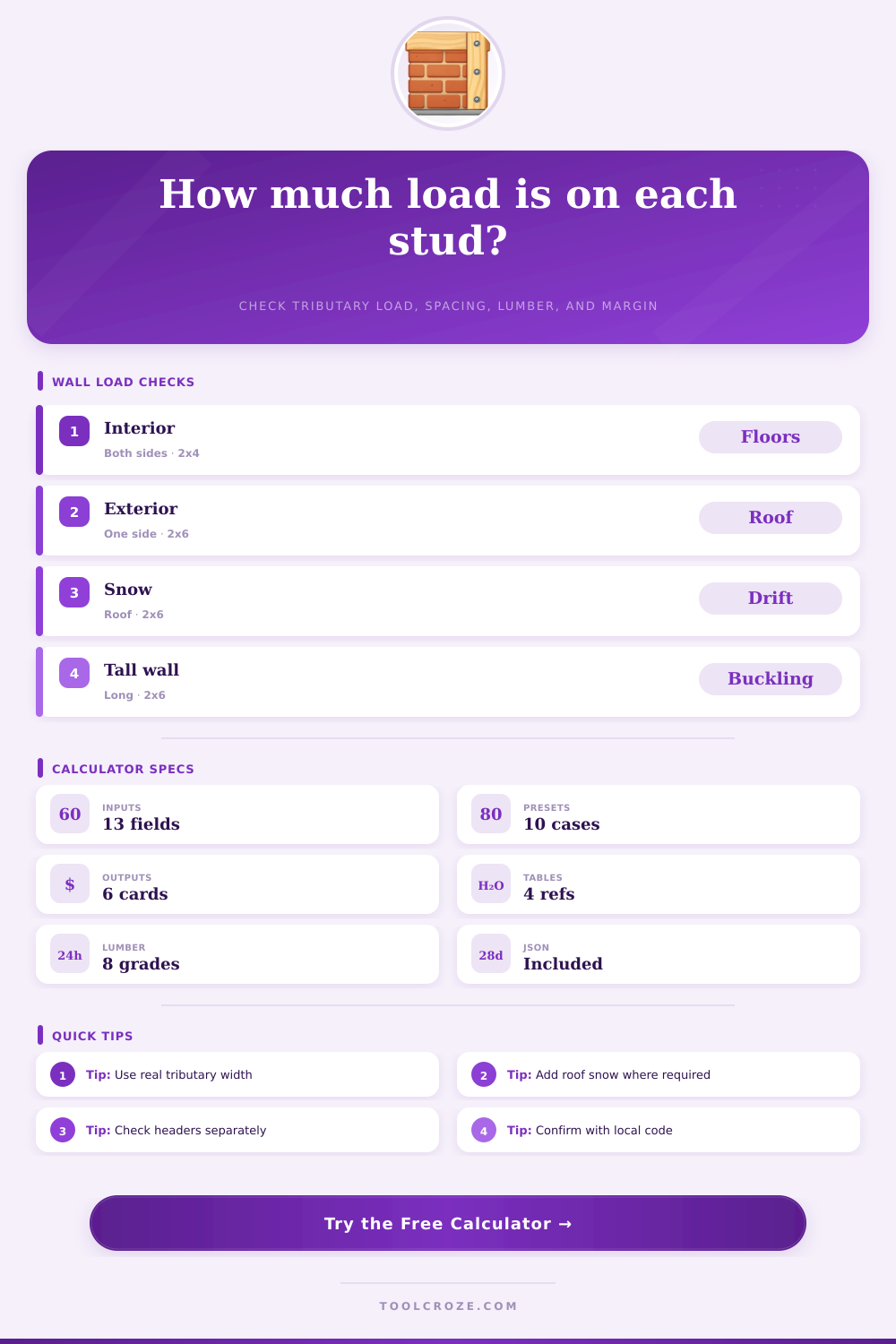
📌Wall Presets
📐Inputs
🧱Selected Lumber Spec Grid
📋Calculation JSON
📚Reference Tables
| Load source | Typical range | Calculator field | Notes |
|---|---|---|---|
| Residential floor live | 30 to 40 psf | Floor live load | Bedrooms often lower than living areas. |
| Floor dead load | 10 to 20 psf | Floor dead load | Tile, topping, or heavy ceilings raise this. |
| Roof live or snow | 20 to 70 psf | Roof live/snow load | Use local snow and drift requirements. |
| Wall self weight | 8 to 18 psf | Wall self weight | Exterior sheathing and cladding add load. |
| Species / grade | Fc estimate | E estimate | Use note |
|---|---|---|---|
| SPF Stud grade | 875 psi | 1.2E6 psi | Common light framing baseline. |
| SPF No. 2 | 1150 psi | 1.4E6 psi | Common residential studs. |
| Hem-Fir No. 2 | 1300 psi | 1.3E6 psi | Check local grade stamp. |
| Douglas Fir-Larch No. 2 | 1350 psi | 1.6E6 psi | Stronger common framing option. |
| Southern Pine No. 2 | 1450 psi | 1.6E6 psi | Often used where available. |
| 1.9E LVL stud | 2300 psi | 1.9E6 psi | Engineered stud, verify product data. |
| Stud size | Actual size | Area | Best use |
|---|---|---|---|
| 2x4 | 1.5 x 3.5 in | 5.25 in2 | Standard low to moderate walls. |
| 2x6 | 1.5 x 5.5 in | 8.25 in2 | Higher load, exterior walls, insulation. |
| 2x8 | 1.5 x 7.25 in | 10.88 in2 | Heavy wall or special framing. |
| 3x4 | 2.5 x 3.5 in | 8.75 in2 | Greater weak-axis area. |
| 3x6 | 2.5 x 5.5 in | 13.75 in2 | Tall or high demand preliminary checks. |
| Wall length | 16 in spacing | 24 in spacing | Comment |
|---|---|---|---|
| 8 ft | 7 studs | 5 studs | Includes end studs. |
| 12 ft | 10 studs | 7 studs | Openings need separate jack/king checks. |
| 16 ft | 13 studs | 9 studs | Line load per stud still uses spacing. |
| 24 ft | 19 studs | 13 studs | Long walls may need bracing checks. |
| 32 ft | 25 studs | 17 studs | Check cumulative settlement paths. |
💡Tips
To determine how much weight will land on each stud in a load bearing wall, there is many different factors that must be considered. A load bearing wall is a wall that helps to transfer the weight of the roof and the floors down into the foundation of the building. Each stud in the stud wall will share in the weight of the building.
If the weight calculations is incorrect, the wall could either be underbuilt (creating a weak point) or overbuilt (spending too much money on construction). A weak point in a wall can lead to sagging floors or cracked finishes in the future. One of the factors that must be calculated is the tributary width of the wall.
How Much Weight Each Stud Will Carry
Walls that are in the interior of a building will receive the weight of the floors from the joists on both side of the wall. The tributary width in these cases will be half the span of the floor on the left side of the wall plus half the span of the floor on the right side of the wall. Exterior walls, however, will only receive the weight of the joists on one side of the wall.
Therefore, the tributary width of exterior walls will be different than interior walls. A calculator can help to determine the correct tributary width of each type of wall. The other factors that must be determined is the live load and dead load of the floors.
The live load of a floor is the weight of the objects that are in the floor, such as furniture and individuals. The dead load of a floor is the weight of the floor itself, such as the joists, subfloors, drywall, and flooring finishes. You can add the live and dead load of floors together to create the total load that each floor exerts on the studs in the wall.
Increasing the dead load of a floor by adding items like tile will increase the dead load that each stud must carry. Therefore, it is necessary to calculate both the live and dead load of floors separately. Another factor to consider is the load of the roof.
The weight of the snow that lands on the roof, the rain that falls on the roof, and the items that are stored on the roof all contribute to the load of the roof. The tributary width of the roof and the load of the roof are different than the tributary width and load of the floors. Therefore, you must enter each of these two factors into a calculator separately.
If the load of the roof is not considered, the calculations for the total load that the studs in the walls must bear will be incorrect. The weight of the wall itself is another factor that must be considered. The self weight of the wall will be significant if the wall is tall and includes heavy cladding.
You must include the weight of studs, plates, sheathing, and the finishes for the wall in calculating the self weight of the wall. For tall stories in a building, the self weight of the wall will act similar to the floor loads and the roof loads to contribute to the total load that the studs must bear. Once you have determined the total line load that each stud must bear, the spacing of studs must be considered.
If the studs are closer together, each individual stud will have less of a load placed upon it. However, using closer spacing for studs will increase the total number of studs that are necessary for the wall. Using wider spacing between studs will increase the load on each individual stud but will decrease the total number of studs that is required for the wall.
A calculator can help to determine if stud spacings of, for instance, sixteen inches on center to twenty-four inches on center would be a good decision for a building. The capacity of the lumber that is to be used for studs will depend on the species of the lumber, the grade of the lumber, and the cross section of the lumber. For instance, studs made of 2×6 Douglas Fir No. 2 will have a different lumber capacity than studs made of 2×4 SPF lumber.
A stud load and lumber capacity calculator can calculate the capacity of the studs. The calculator will output a load ratio for the studs. If the load ratio is significantly below one, the studs will have a comfortabley margin of safety in relation to the load that they will bear.
If the load ratio is close to or greater than one, then you must assess the bracing of the studs or the studs will have to be larger than currently calculate. The tables that are provided for each factor provide typical ranges for each of the factors. You can compare the loads for studs to the tables to ensure that they are within normal bounds for buildings.
Additionally, the tables can help individuals to quickly determine the number of studs that will be required based on the length of the wall and the spacing of the studs. These tables are provided as points of reference for building professionals rather than as the final calculation for the determination of the load of studs in walls. There are other factors in the construction of buildings that may complicate the calculations for the load of studs in walls.
Openings in the walls require headers to distribute the load from the floors to the studs in the studs. Loads from beams or other items of importance to the building will land on studs. Other factors include the need for bracing in foundations, fire separation, and lateral bracing.
Additionally, builders must follow local codes and engineering requirements in the construction of buildings. Each of these factors interact with the loads from the floors and the roof. Before building a structure, it can be helpful to run these calculations to determine various tradeoffs.
For instance, using lumber of a higher grade than necessary can allow studs to be spaced further apart. Additionally, using a post placed in a specific location can help to reduce the load on the remaining studs in the wall. Furthermore, it may be possible to determine whether the load from snow on the roof will have a greater impact on the total load of studs in walls than the dead load of floors.
Using the actual tributary widths, dead loads, and lumber species will help ensure that the load ratio is within a safe range. The calculator can help to test these different sets of assumptions prior to building the studs for the wall. Youll find that the calculation is actualy very easy once you follow the steps.
Dont forget to check the builders notes too. The moddern way to do it is using software.