Lag Screw Capacity Calculator
Estimate withdrawal resistance, lateral single-shear capacity, group load, and combined loading for lag screws installed into wood side grain.
Estimated Lag Screw Capacity
| Wood Member | SG Used | Capacity Effect | Typical Construction Use |
|---|---|---|---|
| Western red cedar | 0.35 | Low withdrawal and bearing | Outdoor trim, light rail parts |
| Spruce-pine-fir | 0.42 | Common baseline for studs | Stud walls, rim boards, blocking |
| Hem-fir | 0.43 | Slightly above SPF | Framing, ledgers, posts |
| Douglas fir-larch | 0.50 | Good bearing and pull-out | Beams, joists, structural framing |
| Southern pine | 0.55 | High softwood capacity | Deck framing, treated posts |
| Structural LVL | 0.55 | Dense engineered reference | Beam side plates and headers |
| Red oak | 0.63 | High withdrawal resistance | Heavy blocking, specialty hardwood |
| White oak | 0.68 | Very high bearing estimate | Timber details, exposed hardwood |
| Nominal Diameter | Decimal Diameter | Typical Pilot Hole | Common Construction Role |
|---|---|---|---|
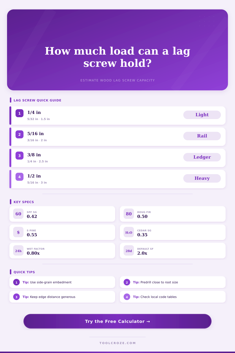
| 1/4 in | 0.250 in | 5/32 in softwood, 3/16 in hardwood | Light brackets and blocking |
| 5/16 in | 0.3125 in | 3/16 in softwood, 7/32 in hardwood | Rail brackets and shelves |
| 3/8 in | 0.375 in | 1/4 in softwood, 9/32 in hardwood | Ledgers, hinge leaves, framing plates |
| 1/2 in | 0.500 in | 5/16 in softwood, 3/8 in hardwood | Heavy posts, brackets, beam plates |
| 5/8 in | 0.625 in | 13/32 in softwood, 7/16 in hardwood | Timber connections and bases |
| 3/4 in | 0.750 in | 1/2 in softwood, 9/16 in hardwood | Large timber hardware and braces |
| Item | Simplified Estimate | Why It Matters | Use With Care When |
|---|---|---|---|
| Withdrawal per inch | 1800 x SG^1.5 x D^0.75 | Approximates side-grain thread pull-out | End grain, splits, or short penetration |
| Lateral bearing | 11200 x SG x angle factor | Higher SG increases dowel bearing | Thin side plates or close edges |
| Angle factor | 1 / (cos^2 + sin^2 / 0.65) | Reduces lateral capacity near 90 degrees | Load is perpendicular to grain |
| Combined check | 1 / sqrt((P/W)^2 + (V/Z)^2) | Blends pull-out and shear demand | Brackets see both uplift and shear |
| Group factor | Quantity x spacing factor | Accounts for non-ideal fastener groups | Rows are close or near member ends |
| Connection | Typical Screw | Wood Member | Screening Notes |
|---|---|---|---|
| Deck ledger to rim joist | 1/2 in lag, 3 in penetration | SPF or treated southern pine | Check prescriptive deck code separately |
| Handrail bracket to stud | 5/16 in lag, 2 in penetration | SPF stud | Usually mixed lateral and pull-out |
| Pergola bracket to post | 1/2 in lag, 3.5 in penetration | Douglas fir or southern pine | Wind uplift can govern |
| Heavy gate hinge | 3/8 in lag, 2.75 in penetration | Cedar or treated post | Repeated cycling needs conservative factor |
| Solar rail to rafter | 5/16 in lag, 2.5 in penetration | SPF or Douglas fir rafter | Roof uplift and waterproofing matter |
| LVL side plate | 1/2 in lag, 4 in penetration | LVL or glulam | Use engineered connector design for final |
Heavy shelving, deck ledgers, and timber framing all require Lag Screws. Think of them as big nails with an added bonus (threads). Why’s that important? Because it makes the lag screw different from a nail. Where a nail merely clings to the face of the wood, the lag bite into the wood fibers and resists movement in two ways: one is called lateral shear strength. That keeps the attached members from slipping relative to each other. Another force, called withdrawal resistance, keeps the screw itself from coming straight out of the wood.
Most of us think they’re the same thing. They aren’t. And knowing how they differ is how you start building a lasting connection. That’s why the calculator (above) does the math for you, but it’s much more helpful if you know what these variables are.
What You Need to Know About Lag Screws
The biggest variable in that equation is something called specific gravity. This basically measures how dense the wood is compared to water. Southern pine can reach a specific gravity of 0.55. These small variations in density equate to large gains in bearing capacity. Using a hard wood number where there was previously a soft wood number isn’t going to give the same results. The calculator recognizes this too and adjusts lateral and withdrawal estimates based on the species you choose. So if you’re using a softer wood like cedar, you have to temper your expectations accordingly. The wood just won’t hold as much load per square inch of thread.
The other place people often get confused at is embedment depth. Builders often think that the entire length of the screw adds to their embedment and therefore the holding power. They don’t. Only the threaded section inside the main member will add to the pull-out strength. Anything outside of the main member (like the part beneath the washer or coming through side plate) will not help at all in pulling out resistance. Rather, it just clamps the joint together.
That’s what you’re setting when you input penetration depth. You are defining the actual depth that’s engaged, and thus how much of it there really is contributing to holding. Therefore, if you drill a three-inch hole, but you can only thread in two inches into main beam, your capacity goes down a bunch! This effective depth is what the calculator takes as its starting point to see how much surface area you really have doing the work for you.
The geometry kicks back in with lateral loading. When a lag screw gets pushed to the side, it behaves like a dowel pin. It becomes the hinge point for the wood and transfers the load to the remaining member. The strength of the wood surrounding the hole is what makes this work. Splitting is the enemy. Pushing a screw too near an edge of the board can cause the wood to tear before the screw will give.
On the page, there’s a reference table that recommends spacing and appropriate pilot holes. Proper spacing gives the wood fibers between the fasteners enough material to carry the stress without failing locally. In fact, tight groupings of screws can be less effective than widely spaced ones as they form a line of weakness that cleanly tears the piece in two.
There’s a reason we have safety factors. Wood isn’t an even substance. Each piece has moisture content differences throughout its length and other irregularities like checks and knots. When you’re designing for half the theoretical strength of the connection (i.e., a safety factor of 2.0), you’re accounting for these imperfections that no calculator can see. You’re covering the inevitable variations in installation quality as well. Too-large pilot holes decrease withdrawal strength. Too-small pilot holes cause the wood to split on drive. Either scenario compromises the connection.
With the tool, you can vary the safety factor depending on how confident you are in both the quality of the work and the material. For example, if the wood is dry and the pilot holes are laid out perfectly, you might bump it down; but if the wood is wet or the layout is tight, bump it up.
There’s also the question of how long the load will be present. Wind gusts are short term; permanent structural loads or accumulative loads (like snow accumulation over time) are not. The calculator takes this fact about wood into account with a duration factor. Something that would survive a 10 year-storm may give out after a decade of continuous load. It doesn’t sound like much, but when you’re down to the wire on whether to go with a safe margin vs. It could lead to a potential failure.
So in conclusion, Lag screw connections are a mix of two materials: wood and metal. One supplies the bearing surface (wood) and the other lends the tensile strength (screw). Neither can be cheated. It’s all about the physics of each material. Layout carefully, pilot drill correctly, and space everything properly. Your tool should tell you what you’re up against. Lay out accordingly and then check yourself. A good hole makes for a good screw.