🔧 Keyway Calculator
Match DIN 6885-A shaft key sizes to a clean shaft depth, hub depth, cutter depth, and pass count before you machine the slot.
📌 Presets
📊 Calculator
🛠 Tooling Grid
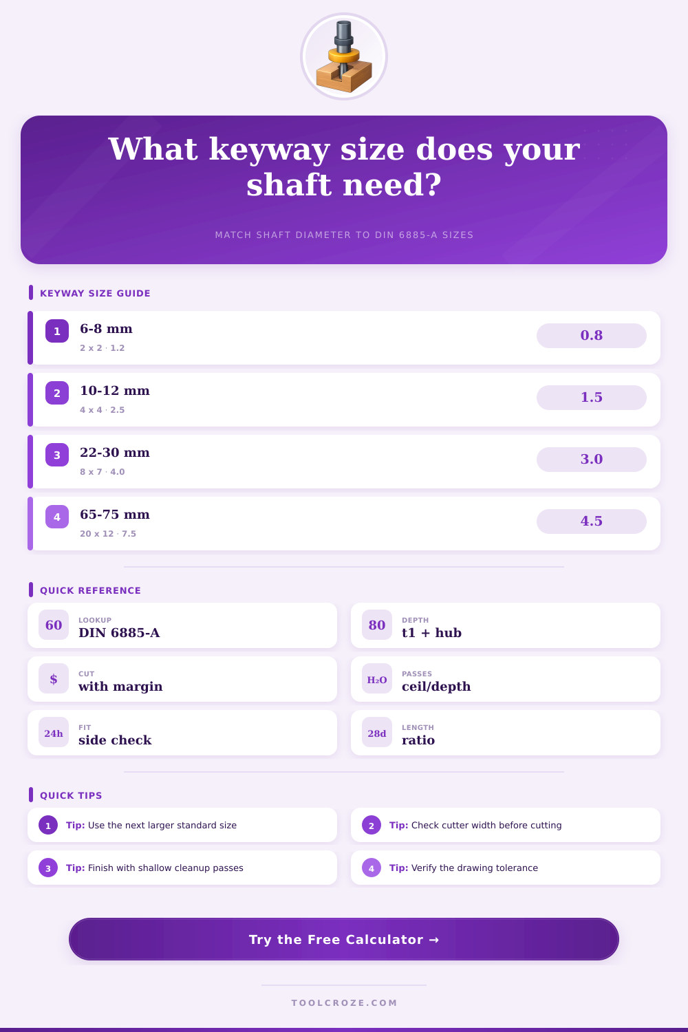
📐 DIN 6885-A Reference Table
| Shaft Diameter | Key Size | Shaft Depth | Hub Depth | Typical Use |
|---|
📊 Fit Reference
| Fit Class | Allowance | Typical Feel | Best Use |
|---|---|---|---|
| Loose | +0.05 mm / +0.002 in | Easy assembly | Field repairs and quick checks |
| Standard | +0.02 mm / +0.001 in | Balanced fit | General workshop keyways |
| Tight | 0.00 mm / 0.000 in | Firm seating | Precision shafts and hubs |
| Hand Fit | 0.00 mm / 0.000 in | Scrape or stone | Final fitting after test assembly |
📝 Formula Reference
| Formula | Meaning | What It Returns | Use |
|---|---|---|---|
| Lookup row | Match shaft dia to table | Key width and height | Standard selection |
| Hub depth | Key height - shaft depth | Nominal hub seat depth | Complementary fit |
| Cut depth | Nominal depth + allowance | Finish-ready depth | Cleanup pass target |
| Pass count | Cut depth / max pass | Rounded up whole passes | Machining plan |
| Engagement ratio | Key length / key width | Length to width ratio | Check key support |
💡 Tips
⚠ Safety Note
📖 Article
This keyway calculator matches shaft size to standard DIN 6885-A rows, checks shaft and hub depths, and estimates pass count so shop setup stays clean and predictable.
Keyways is slots cut into the shafts and hubs for keys. Keyways allows torque to be transmit between the shaft and the hub while ensuring the parts dont slips during operation. Many people uses parallel sided keys that follow the DIN 6885-A standard because the DIN 6885-A standard provides the dimension for keys of all sizes.
If the wrong size of key is selected, the parts may chatter or fail altogether. The dimension of keys are tied to the diameter of the shaft. Additionally, the depth of the shaft is deeper than the hub because of the round ends of the key.
How to Size and Cut Keyways and Keys
The diameter of the shaft will determine the other dimensions of the key. For instance, an 25 mm shaft requires an 8 x 7 mm key, a 4 mm shaft depth, and a 3 mm hub depth. The reason that the shaft and hub depths is different is that the asymmetrical shape of the keyway allow the key to be centered toward the center of the shaft.
By centering the key towards the center of the shaft, the weaker component of the shaft or hub is protected from any damage. These dimensions can be found in a key lookup table based off the diameter of the shaft. This lookup table allow for the proper width, height, and depth of the key to be selected according to the torque capacity of the shaft.
Keyseat cutters works by following the shape of the shaft. This process is used for classic shaft work and allows people to ensure that the shaft depth and the hub depth are correct for each component. The cutter must account for a maximum depth of cut for the workpiece.
Additionally, the cutter must allow for the depth allowance for the finish of the keyseat. The number of passes the cutter makes must be calculated to ensure that the metal chip are within a manageable range and that the heat created during the process is kept to a minimum. Fit class is a measurement that determine the clearance between the key and the keyseat.
The standard depth is used in most applications, but a loose fit is used for field repairs. A tight fit allow for the key to be ground to the shaft and used in components that require a high degree of precision. The cutting tool must be ensured to not exceed the width allowed for that component.
If the cutter is too wide for the component, it will ruin the keyway before the person can become aware of the mistake in the cutting tool. To ensure that the depth of the hub and shaft are equal, the target hub depth can be calculated by subtracting the shaft depth from the key height. If the shaft and hub depths are not calculated correctly, the torque may shear the key.
The length of the key is important to the function of the component. The length of the key must be 1.5 times the width of the key to ensure that it does not falter under reverse loads. The longer the shaft, the more torque it can take, so a longer key is appropriate for high torque application.
Although there are many ways keys and keyways can be used in real-world applications, they may not meet the specification listed in the text. In the example of a 38 mm shaft in a gearbox reducer, the DIN 6885-A standard requires the use of an 8 x 10 mm key and a 5 mm depth for the shaft. If the end mill allow for only 1 mm passes, five roughing passes are required for the shaft, followed by one additional pass to clean up the keyseat.
For one of the gear on a 65 mm pump shaft, the 20 x 12 mm key is used with a loose fit that permits an extra 0.05 mm movement for the key to slide into place within the shaft. Many common mistake can be made in the creation of a keyway. For example, incorrect mathematics will lead to incorrect depths for keys.
Additionally, it is a mistake to force a non-standard depth into a keyway. This will waste the keys and may weaken the component. It is better to allow for the rounded end of the key to have a slight overdimensioning to the next size in the DIN 6885-A standard.
The cutting tool diameter for keys must also be accounted for. For an 8 mm key, no more than an 8.02 mm cutter should be used; otherwise, the sides of the keyway will bind. A professional approach to creating a keyway will involve planning the passes for the cutter.
Using roughing passes to allow for the shaft to not deflect from the cutting tool, then the final passes to square the bottom of the keyway. Additionally, a 0.05 mm allowance should be left for the finish of the keyseat to ensure smoothness of that component; this value will not require a remake of the keyseat. Additionally, it is also possible to engage the key to ensure that the torque requirement for the component are sufficient.
The 32 mm length of the key with an 8 mm width will provide a 4x ratio of the key, which will be sufficient for most drive components. A ratio of less than 1.5x will require the person to rethink the component’s design or to place a setscrew in the component to prevent slippage. The material of the shaft and the hub will also factor into the cutting process.
For softer shaft material like 1045 steel, the worker will make more conservative passes with the cutting tool. Hardened shaft and hub components may create challenges for the cutting tool, as the shaft may gall when the clearances are too small for the hub components. It is a good idea to perform a mockup with a test key to feel how the key slides into the component.
Because DIN standard use ground keys, stock measurements of the components will vary. The burrs on the edge of the components should be chamfered lightly; otherwise, the key may hang up on the burrs in the component. Standards such as DIN 6885-A were created to prevent the failure of components with keys.
The deeper shaft seats and the tapered length of the keys are included to prevent stripping of the key components under shock load. Additionally, the shallower depth of the hubs is to preserve the strength of the hub bore. Moddern standards ensure that people understands these design choices.
For instance, a 150 mm shaft will require a 36 x 20 mm key and a 12 mm depth for the shaft. For these dimensions, a broach cut may be used for high volume of production, or a slotter cutter may be used for one-off manufacturing of parts. When manufacturing these component, there are warnings that should be looked at prior to beginning the manufacturing process.
For instance, if the shaft is undersized, the standard will default to a small key. If the shaft is oversize, an engineering review of the component is required. If the cutter does not match the size of the key, the cutter will halt the manufacturing process.
Additionally, if the length of the key is too short, a torque double-check is required. These warnings will provide insurance for the person working in the workshop. Following the lookup table, planning the passes of the cutter, and even making a mockup model, the keyway will be precise and the shaft will be able to transmit the torque to the component without any issues.